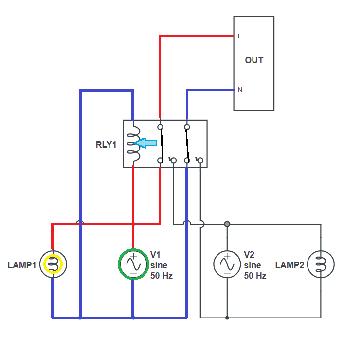
The circuit is essentially just this. When the primary input (V1) is powered, it energises the relay coil and pulls the contacts toward it, connecting the primary supply to the outputs. When the primary input is not powered, the relay coil de-energises and selects the secondary.
Here& #39;s it is again with the energised path showing for when the primary input is powered. Notice how the secondary input is completely isolated, even in the second diagram when both are on. It doesn& #39;t matter - if the primary input is on, it will be used.
It& #39;s only when the primary is unpowered that it& #39;ll switch back to using the secondary, because the relay coil is de-energised.
One double-edged sword here is that relays have a travel time, where the switch side is connected to neither terminal. The good thing about this is that it can& #39;t bridge the two inputs together, feeding power between them - that would be dangerous. But this causes a short delay.
During the delay, known as the switching time, there& #39;s no power going to the output - it& #39;s completely disconnected. You& #39;ve effectively turned off the output. If the switching time is too long, your devices will power off whenever there& #39;s a switching event. Not ideal.
The relay in this device is a Schrack (now TE Connectivity) RM805730. The datasheet shows that the maximum switching time is 15ms for energising, and 10ms for de-energising. Means you lose a maximum of 75% of an AC cycle for the UK& #39;s 50Hz mains frequency.
The calculation is simple: 50 cycles per second, 1000 milliseconds per second, so one cycle period is 1000/50 = 20ms. 15ms is 75% of that.
Most computer equipment power supplies will withstand at least a single cycle of power loss before shutting down, in normal situations.
Most computer equipment power supplies will withstand at least a single cycle of power loss before shutting down, in normal situations.
It also comes with this warning label on the front, telling you not to connect two different power phases as inputs.
The reason is that if there& #39;s a switchover event, you can get voltage discontinuities. Consider two AC inputs from two different phases from the grid. They& #39;re 120 degrees out of phase with each other. In this graph, the vertical range is volts, the horizontal is milliseconds.
Imagine that the switching time is actually shorter than 10ms (that& #39;s the max switching time for de-energising the coil) - say just 5ms. What you get is a weird voltage waveform that looks like the green line.
This is a problem. Power supplies are designed to have a certain maximum dV/dt (i.e. the maximum gradient of the voltage, or change in voltage per given time period) and this jump results in a full peak-to-peak swing occurring in a much shorter time than it should.
But it can be even worse! Imagine if the switch-over happened a little later. Now you miss the entire negative side of the wave and get two positive sides in a row!
This can lead to all sorts of problems in power supplies and potentially cause them to power down in the event of switch-over, which is what the ATS is supposed to prevent in the first place.
You can more safely switch across phases if you perform zero-crossing detection, and only switch once you detect that the secondary input has reached the same half of the curve as the primary was on when it failed, but this extends the switching time a bit.
The fancier approach is to have all three phases going into your UPS, so you don& #39;t need this kind of swap-over. If one phase dies you can either maintain power off the other two, or switch to battery.

 Read on Twitter


