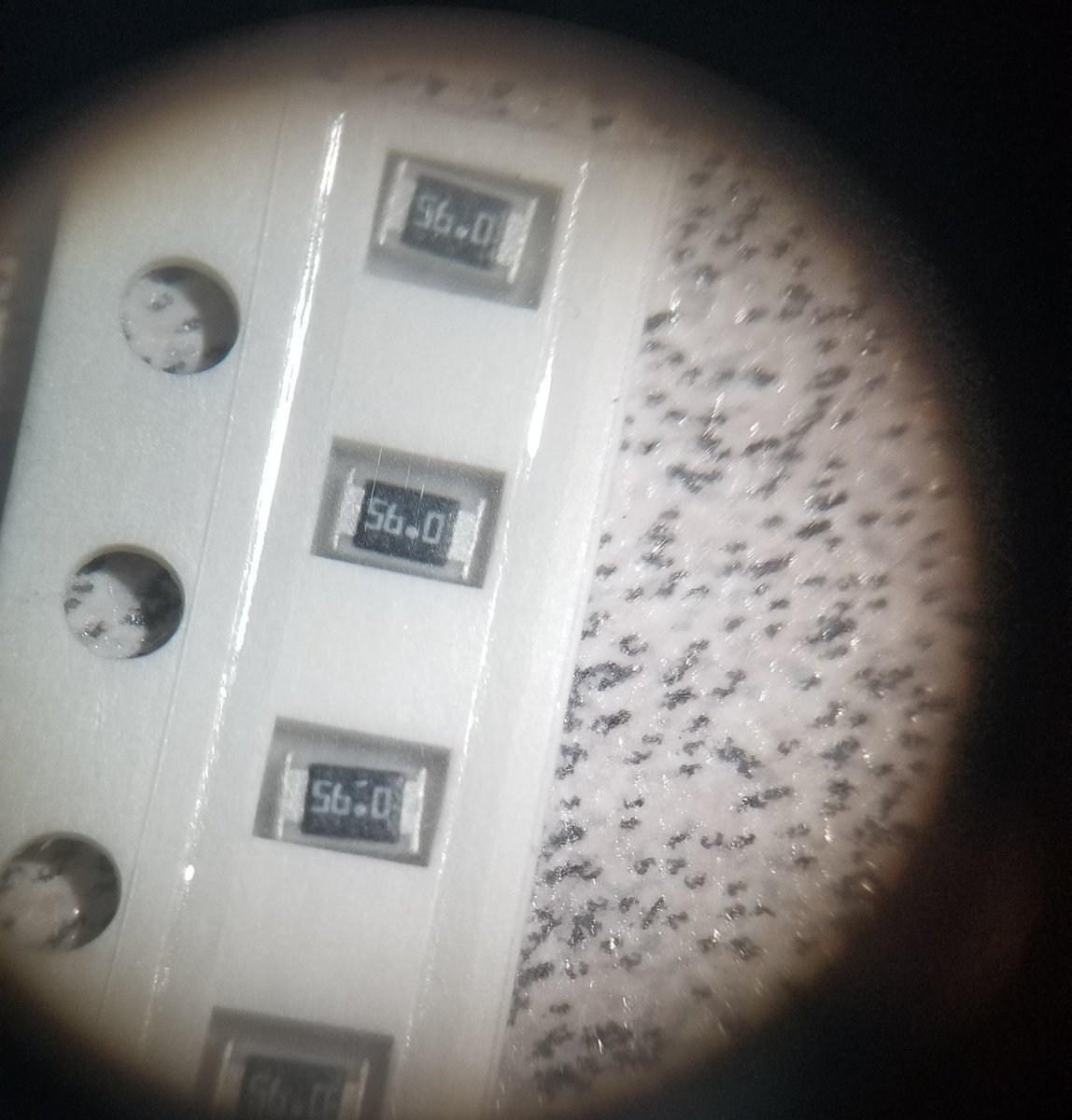
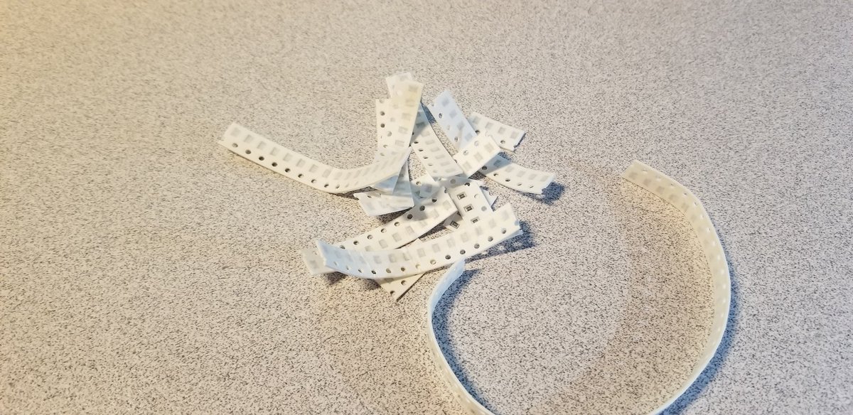
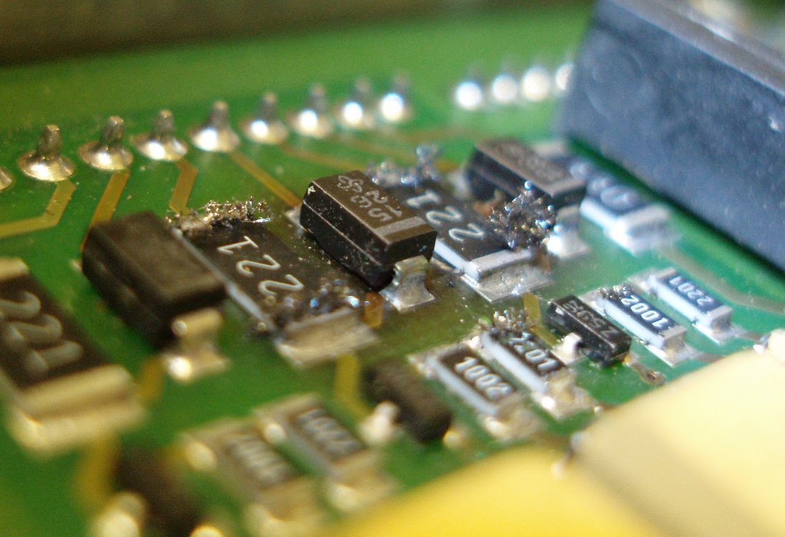
You know you& #39;re having a good day when you have the microscope out so you can sort some smd resistors that got mixed up
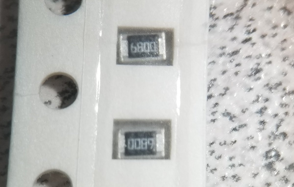
here& #39;s some 6800s... or 0089s?
My favorite thing about SMD resistor labeling:
This project has plenty of 1000 ohm resistors, right?
And these are labeled 1000!
but they& #39;re not 1000 ohm resistors.
This project has plenty of 1000 ohm resistors, right?
And these are labeled 1000!
but they& #39;re not 1000 ohm resistors.
so the way 3/4 digit SMD resistor labeling works is that "R" means ".", and the last digit is 10 to that power.
so 1000 is actually "100 times 10⁰"
ten to the zeroth is of course 1, so these are actually 100 ohm. 1000 ohm resistors are therefore labeled 1001.
the R thing is for resistors like 0.5Ω, which& #39;d be labeled 0R5
Naturally this standard is nice and only slightly confusing so there& #39;s another standard to choose from.
That& #39;s EIA-96, which is based on 3 characters: Two digits and a letter.
The letter is a multiplier.
That& #39;s EIA-96, which is based on 3 characters: Two digits and a letter.
The letter is a multiplier.
SEE the really fun thing about EIA096 is that the numbers aren& #39;t... numbers. They& #39;re not telling you the first two digits of the value, so 38C isn& #39;t just 38*100, it& #39;s actually a code lookup. It& #39;s the 38th EIA-96 value, which is, of course, 243.
BTW if this isn& #39;t confusing enough, EIA-96 is one of those fun "standards" where it& #39;s not standard.
Different manufacturers will use different letters. FORTUNATELY this mostly seems to be two schemes. And guess what: Those two schemes are NOT overlapping!
Hurray!
Different manufacturers will use different letters. FORTUNATELY this mostly seems to be two schemes. And guess what: Those two schemes are NOT overlapping!
Hurray!
The two schemes really only come down to 3 letters:
0.01 and 0.1 are either "Y/X" or "R/S".
And confusingly, 10 is usually B but sometimes H.
Since the letters normally only go up to F, that& #39;s not ambiguous
0.01 and 0.1 are either "Y/X" or "R/S".
And confusingly, 10 is usually B but sometimes H.
Since the letters normally only go up to F, that& #39;s not ambiguous
EXCEPT HERE& #39;S THE THING: You know how I said it& #39;s not ambiguous? well, technically that& #39;s true, and also not.
EIA-96 is not ambiguous with other variations on EIA-96.
But one variant CAN be ambiguous with the 3 digit system.
EIA-96 is not ambiguous with other variations on EIA-96.
But one variant CAN be ambiguous with the 3 digit system.
because normally 3-digit is just gonna be like 582 and EIA-95 is going to be like 45F and those aren& #39;t ambiguous at all.
One& #39;s digits, and one& #39;s letters.
One& #39;s digits, and one& #39;s letters.
Except 3/4-digit does actually use one letter: R, because decimal points.
And EIA-96 wouldn& #39;t be ambiguous with that if they always used ZYXABCDEF... but sometimes instead of Y they use R, and WHOOPS AMBIGUITY
And EIA-96 wouldn& #39;t be ambiguous with that if they always used ZYXABCDEF... but sometimes instead of Y they use R, and WHOOPS AMBIGUITY
SMD Capacitors have a fun variation where they pre-scaled the whole system.
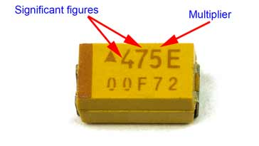
So you have 3 digits and they& #39;re two digits + 10-to-the-third-digit, but instead of being farads, they& #39;re picofarads.
So you have 3 digits and they& #39;re two digits + 10-to-the-third-digit, but instead of being farads, they& #39;re picofarads.
so that one decodes to 4,700,000, but since it& #39;s prescaled, it actually means 4.7 µF.
fortunately the vast majority of SMD capacitors use a different labeling scheme that isn& #39;t confusing at all, isn& #39;t ambiguous, and doesn& #39;t ever require looking up information on the internet!
Great, right?
NO!
Great, right?
NO!
They just don& #39;t label them at all.
this is great because if you have a selection of capacitors of different sizes for a project and you accidentally drop the box and get them all confused together, your best option is to go back to the store and buy more.
BTW, remember how I told you that SMD resistors use a 3 or 4 digit system, with R as a decimal, or they use EIA-96, which is two digits and a letter?
REMEMBER HOW THIS THREAD STARTED? https://twitter.com/Foone/status/1309603765977149440">https://twitter.com/Foone/sta...
REMEMBER HOW THIS THREAD STARTED? https://twitter.com/Foone/status/1309603765977149440">https://twitter.com/Foone/sta...
yeah, see apparently some resistor makers just give up on either of the 2.5 standards and write out resistors in the 1-99 ohm range as-is, with a real decimal.
Remember kids, every standard is terrible and confusing and you should fix it by inventing a new standard.
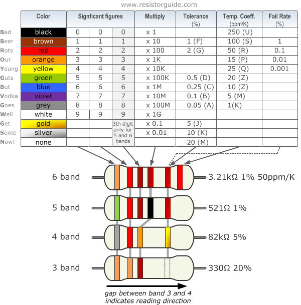
BTW, non-SMD resistors, which are much bigger and have much more room for labeling, solve this whole problem by using a similar code but instead of digits they use colors, because fuck the colorblind, you know?
fun fact: Because there& #39;s no natural ordering of colors (like their is for letters or numbers), this requires memorizing the color order. This has traditionally been done my mnemonics!
And if this whole thing wasn& #39;t bad enough yet... many of those are horribly offensive!
And if this whole thing wasn& #39;t bad enough yet... many of those are horribly offensive!
because confusingly indicating it was bad enough, we had to make it unreadable if you were colorblind, then teach people to remember the color order using sexist and/or racist mnemonics.
You basically have to remember the order "black brown red orange yellow green blue violet gray white", and so you get ones like "Bad boys rape our young girls but Violet gives willingly".
and that& #39;s the "cleaned up" version. The first B used to be Black.
and that& #39;s the "cleaned up" version. The first B used to be Black.
and you& #39;d think this would just be one bad mnemonic someone came up with and a lot of people made variations on but NOPE! there are other bad mnemonics that are clearly created differently.
for example there& #39;s the not racist, not sexist, but possibly intended to be homophobic:
"Batman blows Robin on yon Gotham bridge; Very good Wayne! Get Superman Next!"
"Batman blows Robin on yon Gotham bridge; Very good Wayne! Get Superman Next!"
don& #39;t get me started on Seduction of the Innocent.
anyway the correct way to memorize the color coding is simple, use the following, non-offensive mnemonic:
"Fuck It, Get Your Multimeter"
"Fuck It, Get Your Multimeter"
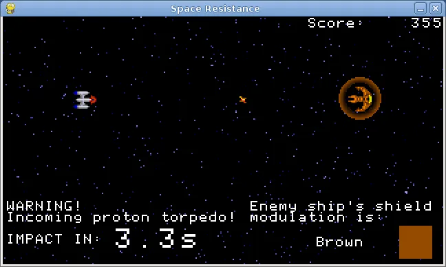
fun fact: a decade ago I made a game for my Game-A-Month project that was EDUTAINMENT designed to quiz you on color codes. You had an enemy ship shooting at you, and you could only defeat them by matching resistor color codes (to their shield frequencies)
BTW to clarify if you& #39;re not into electric assembly, SMD is "Surface-Mount Device".
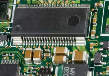
Surface-Mount Devices (or Surface-Mount technology) is a way to attach electrical components to circuit boards, which is soldering them to the surface.
Surface-Mount Devices (or Surface-Mount technology) is a way to attach electrical components to circuit boards, which is soldering them to the surface.
You can see here some cihps and capacitors and how they& #39;re sitting on top of the board.
basically the board is designed with little pads on it to connect to components of the appropriate size.
The rest of the board is coated in solder mask, which keeps the solder paste from attaching to it.
The rest of the board is coated in solder mask, which keeps the solder paste from attaching to it.
after paste has been applied to the board, the components are placed on top of the paste (and they stay because the solder is pretty sticky)
Then it& #39;s headed up (in a reflow oven or with a hot air rework station) which causes the solder to melt
Then it& #39;s headed up (in a reflow oven or with a hot air rework station) which causes the solder to melt
once it cools back down, the solder hardens, and now it has formed a strong electrical and physical connection.
So it now holds the components on the board and connects them to it electrically.
So it now holds the components on the board and connects them to it electrically.
SMD is called that to distinguish it with the older through-hole technology.
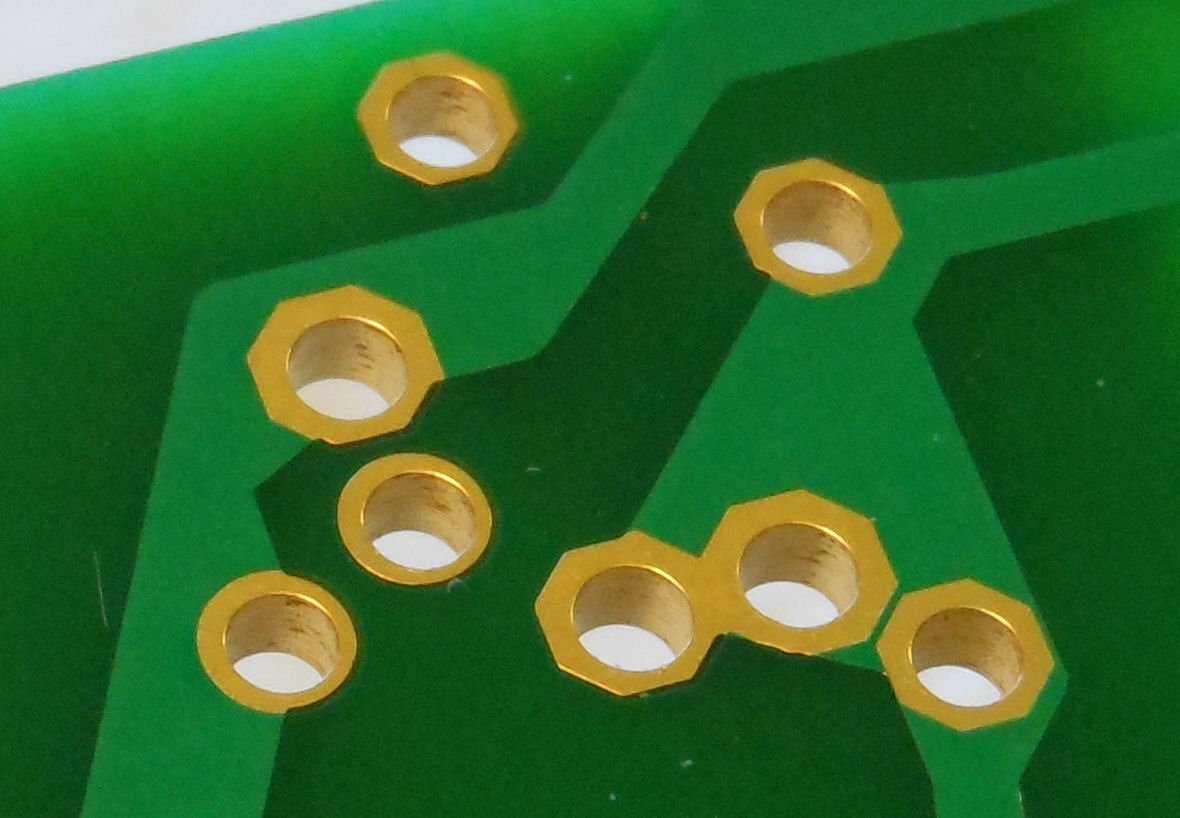
For through-hole, you instead have lots of little holes in the PCB, called "plated-through holes". They& #39;re plated with some conductive material, often gold.
For through-hole, you instead have lots of little holes in the PCB, called "plated-through holes". They& #39;re plated with some conductive material, often gold.
For through-hole, you place the pins of the component through the hole, then apply solder to it with a soldering iron.
this forms solder joints which do the same thing as the SMD ones: electrical and physical connection to the board.
through-hole is nice because it& #39;s comparatively real easy for humans to do. everything& #39;s big and easy to manipulate, the tools needed are cheap, and you can easily prototype and modify boards.
Surface mount, in comparison, is nice for almost exactly the opposite reasons:
It& #39;s easy for machines to do, and everything is small.
It& #39;s easy for machines to do, and everything is small.
since everything in SMD is placed on top, you don& #39;t need to worry about things like feeding the pins through the connectors.
You can easily have a board, apply solder paste using a stencil, have a pick-and-place drop all the components onto it at the right places, then the whole thing goes through a reflow oven, which melts the solder and attaches everything.
which makes it possible to do this in a fully automated (or mostly-automated) assembly line.
Which makes it a lot cheaper to mass-produce these things.
Which makes it a lot cheaper to mass-produce these things.
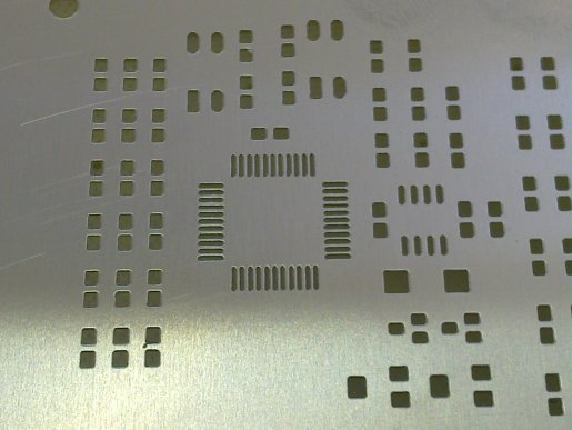
stencil masks, btw, are basically just a piece of metal that& #39;s got holes cut into it to match up with the pads on the PCB.
So you can apply solder paste to it and it& #39;ll only end up on the parts of the PCB that need it.
So you can apply solder paste to it and it& #39;ll only end up on the parts of the PCB that need it.
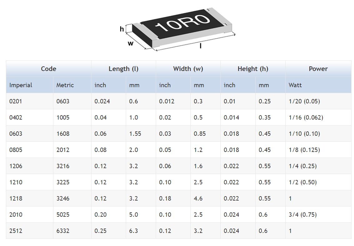
fun fact about SMD capacitors and resistors: They& #39;re available in different sizes. the package code is a 4 or 5 digit number, and it& #39;s just the length and width, with two or 3 digits each.
So a 0603 package is 0.6mm by 0.3mm.
So a 0603 package is 0.6mm by 0.3mm.
all of which would be fine except for two things:
1. You also have imperial sizes, not just metric.
So a 3216 (3.2mm by 1.6mm) is also called a 1206, because it& #39;s 0.12" by 0.06"
1. You also have imperial sizes, not just metric.
So a 3216 (3.2mm by 1.6mm) is also called a 1206, because it& #39;s 0.12" by 0.06"
2. among the common sizes is the 0603 metric and the 0603 imperial.
THOSE ARE COMPLETELY DIFFERENT SIZES!
THOSE ARE COMPLETELY DIFFERENT SIZES!
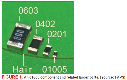
Here& #39;s a comparison of 0603 (imperial) with 0201, which is the same as 0603 metric.
I have screwed this up before, and gotten 0603 metric when I wanted 0603 imperial, and you can see how Fucking Tiny 0603 metric is. You& #39;ll have to click through, the sequence of images is the point. https://twitter.com/Foone/status/1268425665621049344">https://twitter.com/Foone/sta...
Anyway SMT soldering is not fun for humans to do but it makes a lot of electronics cheaper and smaller. You would have a lot of trouble building a mobile phone with through hold soldering, for example.
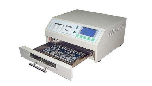
Reflow ovens are a fun part of the SMD soldering process.
They& #39;re basically a little box with a heater in and some sensors, which make sure it heats up the right amount, stays hot for the required amount of time, and then cools it down.
They& #39;re basically a little box with a heater in and some sensors, which make sure it heats up the right amount, stays hot for the required amount of time, and then cools it down.
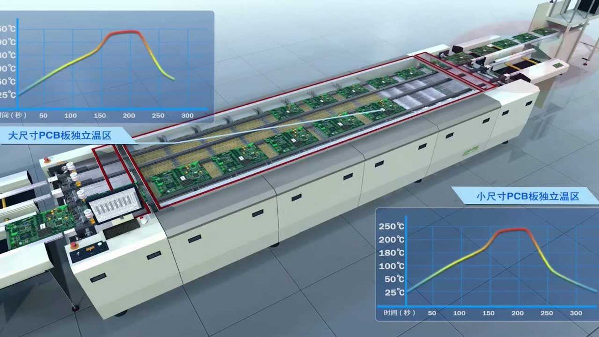
and the cool thing about them is that you can build like that, designed for hobbyists and small production runs, or you can extend them out to a huge machine with a conveyor belt in it, which reflows 20 boards at once and can be fed continuously from one end.
so if you want to upgrade from doing 5 PCBs and hour to 500, you just need to buy some bigger reflow machines, instead of hiring 100 more soldering techs.
the REAL fun thing about smaller reflow ovens is that they& #39;re a small box that has to heat up a certain amount for a certain time...
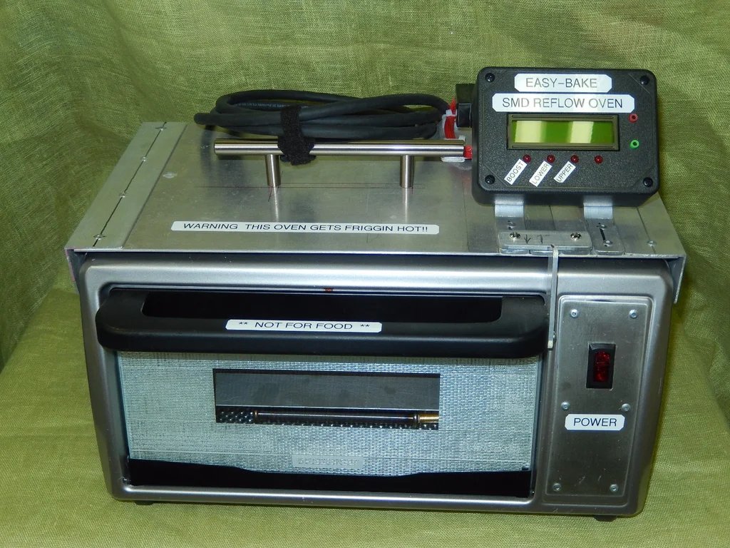
which is basically exactly what a toaster oven is.
which is basically exactly what a toaster oven is.
So it& #39;s entirely possible to DIY together a reflow oven by adding a microcontroller, thermometer, and control circuit.
in ENTIRELY UNRELATED NEWS I may have just bought a toaster oven
That picture btw is from this instructables: https://www.instructables.com/id/Making-A-SMD-Reflow-Oven/">https://www.instructables.com/id/Making...
BTW, one particular type of SMD mount that you often hear about because of problems is BGA: Ball Grid Array.
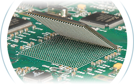
This is a way to connect chips with a lot of connections to a PCB, by using a lot of little balls of solder underneath it.
This is a way to connect chips with a lot of connections to a PCB, by using a lot of little balls of solder underneath it.
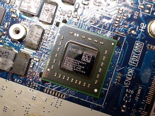
BGA is a way to get a very dense connection between a chip and board, so it gets used for a lot of things like main CPUs and GPUs and such.
If you& #39;re reading this on a laptop or mobile phone, your CPU is probably BGA.
If you& #39;re reading this on a laptop or mobile phone, your CPU is probably BGA.
BGA has two main problems which are why it has a somewhat negative reputation (among non-engineers, even!), despite the wide usage of it:
1. you can& #39;t inspect it easily.
Soldering is not a perfect process, sometimes there are issues.
With BGA, that fault is hidden under the chip
1. you can& #39;t inspect it easily.
Soldering is not a perfect process, sometimes there are issues.
With BGA, that fault is hidden under the chip
2. The chip is very tightly bound to the PCB, and cannot really flex or stretch. This is a problem because as devices heat up and cool down, all the different materials expand and contract at different rates.
so as BGA devices go through heating and cooling cycles, they can put a lot of stress on the components as they bend and stretch differently.
So BGA chips can just fail after enough cycles, as the PCB or chip cracks, or the solder balls lose connection.
So BGA chips can just fail after enough cycles, as the PCB or chip cracks, or the solder balls lose connection.
this is why there& #39;s that folk-remedy of sticking your GPU/motherboard into the oven and going through a reheating cycle.
It may melt those solder balls and let them reconnect, so occasionally it& #39;ll actually revive a broken component.
It may melt those solder balls and let them reconnect, so occasionally it& #39;ll actually revive a broken component.
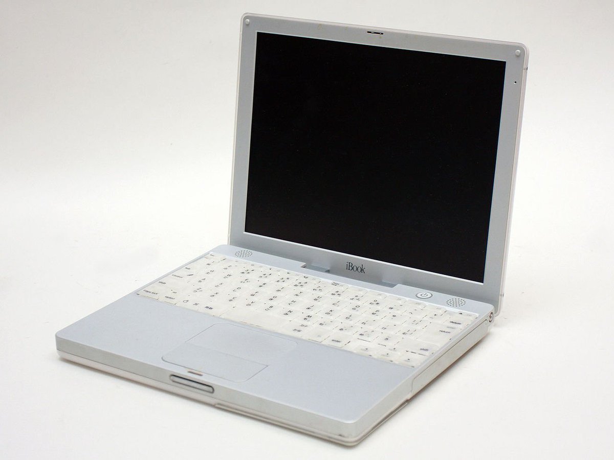
FUN FACT: The laptop I got for college, an iBook G3 Dual-USB, had a really bad problem with BGA fractures.
The GPU chip apparently had significant quality problems with the BGA soldering to the main board, so the display would eventually die on nearly all of these.
The GPU chip apparently had significant quality problems with the BGA soldering to the main board, so the display would eventually die on nearly all of these.
This was discovered and apple had to replace a lot of these, but there were also remedies designed by fans, for after the replacement period ended.
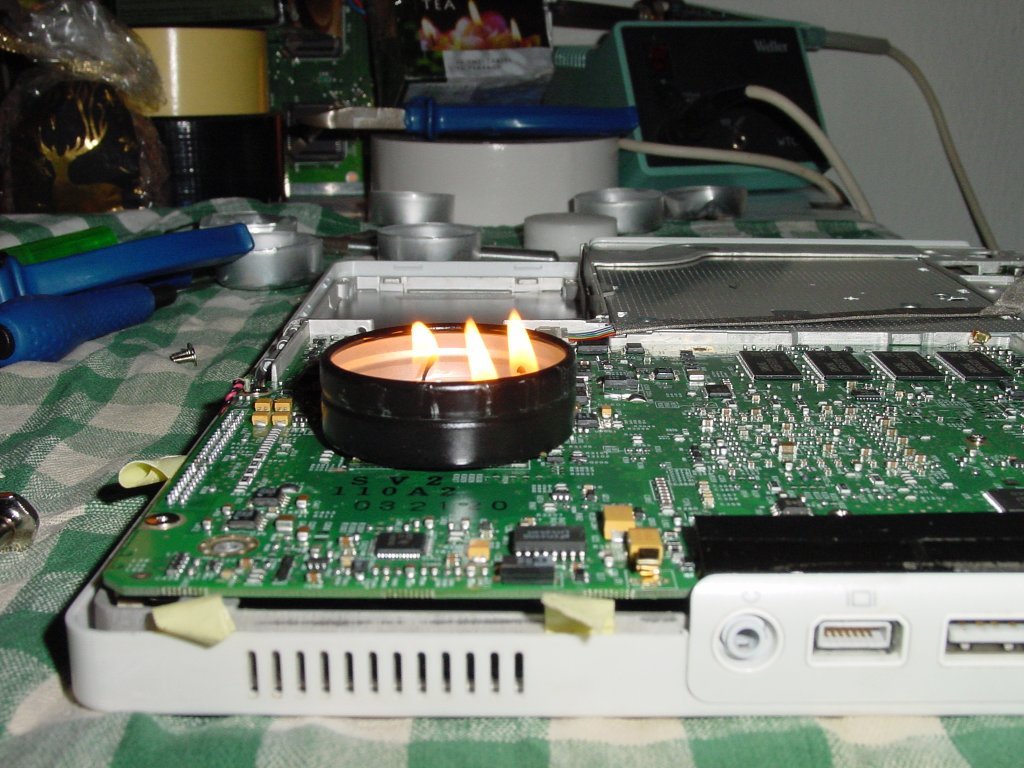
My favorite one involved a candle...
My favorite one involved a candle...
BGA reflow machines are expensive, but you just need to heat up the whole chip a certain amount for a while.
So why not get a candle with a metal cannister, place it on top of the GPU, and fill it with alcohol and light it?
So why not get a candle with a metal cannister, place it on top of the GPU, and fill it with alcohol and light it?
Here& #39;s the details on how that fix worked:
https://www.geektechnique.org/projectlab/726/diy-obsolete-ibook-logic-board-repair.html">https://www.geektechnique.org/projectla...
https://www.geektechnique.org/projectlab/726/diy-obsolete-ibook-logic-board-repair.html">https://www.geektechnique.org/projectla...
Anyway, reflow soldering is fun because you& #39;re heating up the entire board & components, which means you have to be careful about how long things stay hot and how hot they get. (With through-hole, you& #39;re mostly just heating up the pins/wires, not the whole thing)
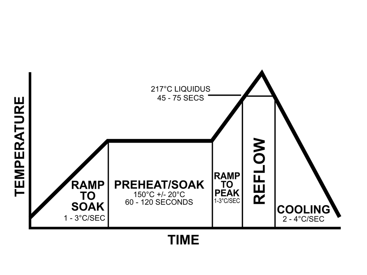
So the reason you need a microcontroller for building a DIY reflow oven is that your solder is going to have a reflow profile, like this:
You bring the whole board up to a "soak" temperature, leave it there fore a while, then temporarily hit a higher reflow temperature to melt it
You bring the whole board up to a "soak" temperature, leave it there fore a while, then temporarily hit a higher reflow temperature to melt it
So you have to be able to control how hot the board is at all times, and not deviate too much from this profile.
If it& #39;s not hot enough for long enough, you& #39;ll not melt all your solder paste.
Too hot and it flows too much, and won& #39;t be in contact with all the parts anymore.
If it& #39;s not hot enough for long enough, you& #39;ll not melt all your solder paste.
Too hot and it flows too much, and won& #39;t be in contact with all the parts anymore.
You also have to coordinate this with your components.
Some components may be damaged by these temperatures, or may break if heated up too quickly/cooled down too quickly.
Some components may be damaged by these temperatures, or may break if heated up too quickly/cooled down too quickly.
This can be a problem when combining different components of different ages together, because of modern solder paste that doesn& #39;t have lead in it.
Solder is a alloy of a couple metals, like tin/lead, tin/silver/copper, or pure tin.
Solder is a alloy of a couple metals, like tin/lead, tin/silver/copper, or pure tin.
The ones with lead in them have a lower melting point, so components designed when lead-based solders were common can have maximum temperatures that are lower than the required temperatures to reflow lead-free solders.
so you end up in a catch-22 situation where you can& #39;t pick any temperature to use, because your solder won& #39;t melt until it hits 220°C but your component breaks if you heat it above 200°C
In any case, the switch to lead-free solder has reportedly been responsible for a lot of problems with electronics in the mid-2000s.
A lot of devices started being assembled with lead-free solders, and the differences in temperatures, chemistry, and long term metallurgy were not understood completely.
not to sound like "THE LEAD KIND WAS JUST BETTER AND WE SHOULD GO BACK" but rather it& #39;s more that lead-free solder has differences that weren& #39;t fully understood by everyone at the time and a lot of devices ended up dying because of that.
One of the best well known problems caused by the switch over is tin whiskers (which confusingly doesn& #39;t just involve tin).
This is a not-fully-understood phenomenon where components start growing metallic crystals
This is a not-fully-understood phenomenon where components start growing metallic crystals
it sounds like an SCP creepypasta but yes, electronics grow. This was first discovered in the 1940s, and it happens to a bunch of different metals, very slowly.
Usually it causes problems when thin tendrils grow out of parts and then break off, and end up landing somewhere and causing a short and damaging the circuit.
Like I said, it& #39;s not understood completely why this happens, but it& #39;s also been observed that lead slows it down.
Like I said, it& #39;s not understood completely why this happens, but it& #39;s also been observed that lead slows it down.
BTW the "lead-free solders are higher temperature" statement isn& #39;t 100% true, there& #39;s lead-free solders which have even lower melting points because of different additives.
It& #39;s never been confirmed as far I know, but I& #39;ve seen suggestions this was the problem with the Apple iBook BGA failures:
They needed to switch to a lead-free solder because of EU regulations, but the chip they were soldering had restrictive temperature requirements
They needed to switch to a lead-free solder because of EU regulations, but the chip they were soldering had restrictive temperature requirements
So they ended up using one of the lead-free solders with additives to lower the melting point to keep it safely under the max-temp of the chip, but accidentally went too far, effectively.
The lead-free solder they used could partially melt after long-term exposure to lower temps
The lead-free solder they used could partially melt after long-term exposure to lower temps
which is a problem for a laptop GPU that is in a system without a great cooling system.
So the chip got quite hot, and slowly over time it would desolder itself from the board.
So the chip got quite hot, and slowly over time it would desolder itself from the board.
Like I said, I don& #39;t know if Apple ever officially confirmed that, but that& #39;s what I& #39;ve heard from the fans having to do DIY repairs to their iBook G3s.
BTW, the specific problem with lead in solder is not that you& #39;ll get lead exposure from your electronics, directly. It& #39;s bound up inside the electronics so unless you& #39;re opening them up and trying to saw through them, the lead is safely contained.
the issue is that a lot of electronics get thrown out and end up in landfills, and there& #39;s a worry that all that lead will slowly leach out of the components and end up in the groundwater.
BTW: lead-free solder is also possibly to blame for the xbox 360 red ring of death.
Similar to Apple, Microsoft has never officially announced why it happened, but one theory is that there& #39;s a problem with lead-free solder on the video chip becoming brittle and cracking
Similar to Apple, Microsoft has never officially announced why it happened, but one theory is that there& #39;s a problem with lead-free solder on the video chip becoming brittle and cracking
anyway I& #39;m gonna stop talking about soldering and start doing it, probably.
if you enjoyed this thread and found it informative, feel free to send me a dollar or two on ko-fi, because I need to buy a lot more soldering tools https://ko-fi.com/fooneturing ">https://ko-fi.com/fooneturi...
if you enjoyed this thread and found it informative, feel free to send me a dollar or two on ko-fi, because I need to buy a lot more soldering tools https://ko-fi.com/fooneturing ">https://ko-fi.com/fooneturi...

 Read on Twitter