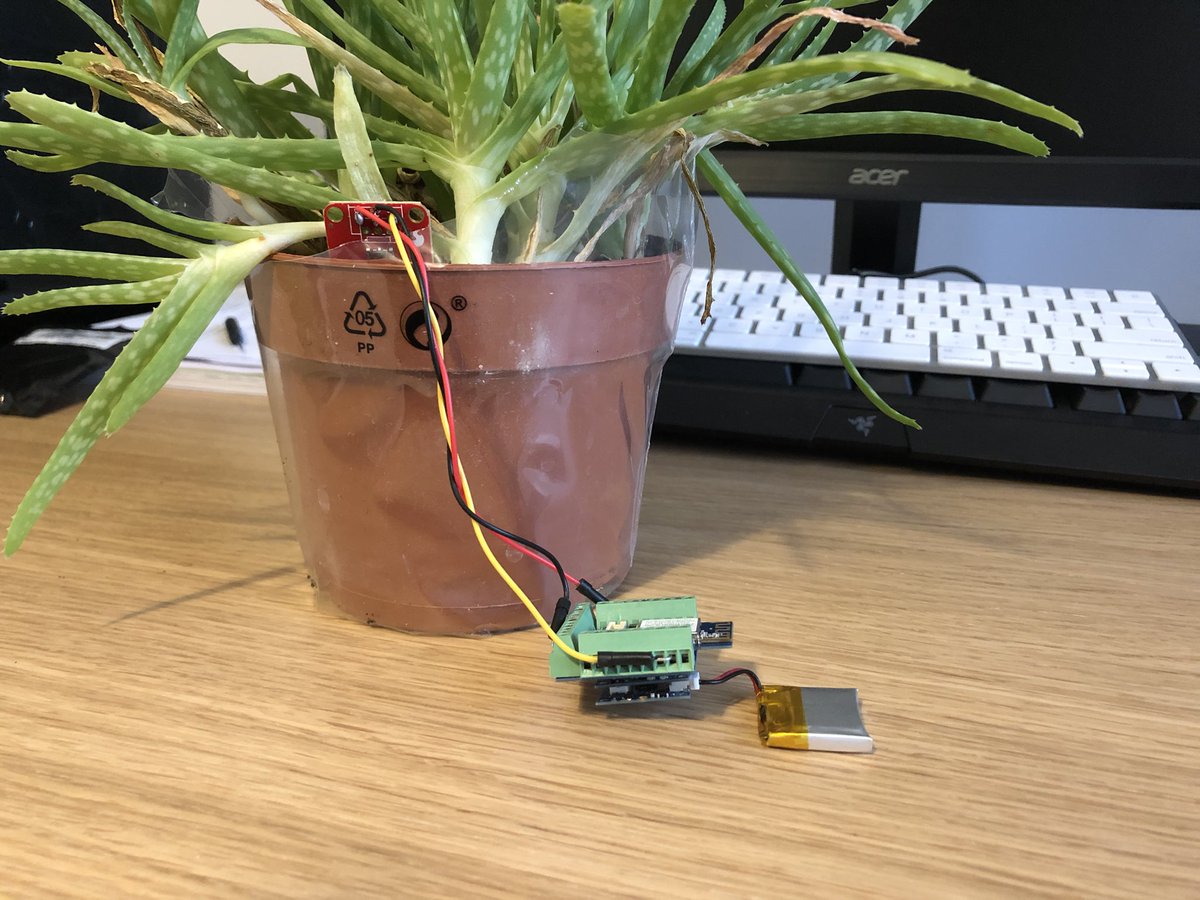
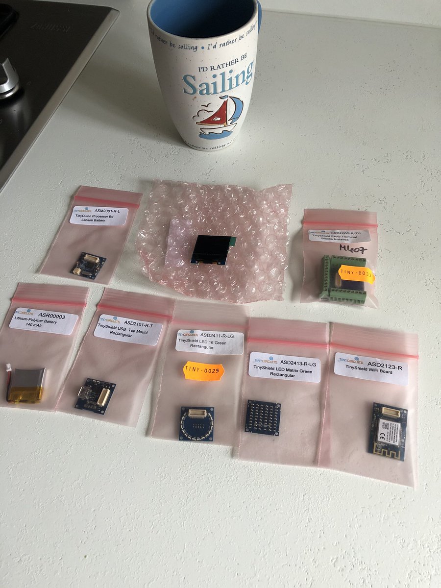
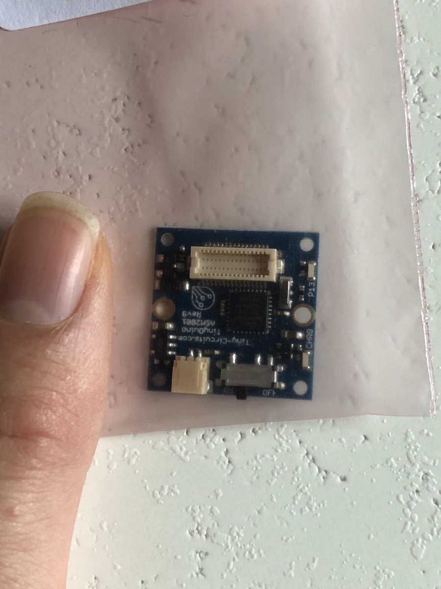
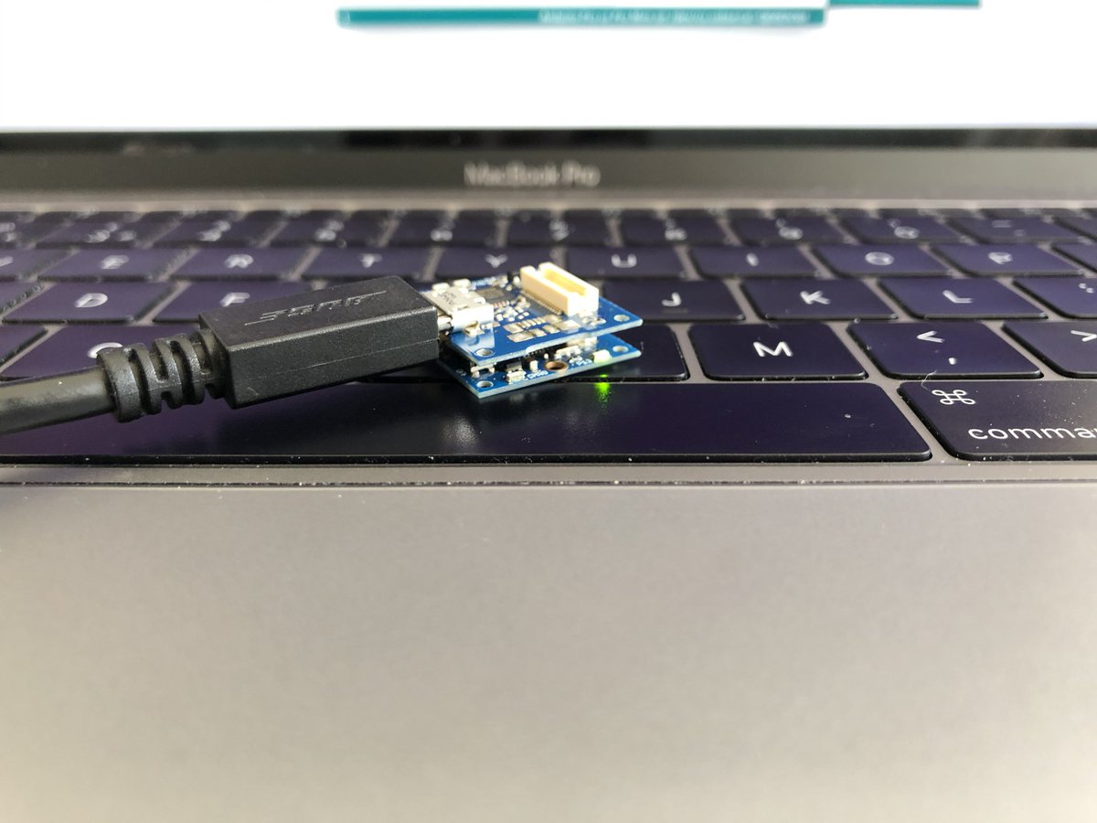
I can’t believe how small the TinyDuino is  https://abs.twimg.com/emoji/v2/... draggable="false" alt="😳" title="Errötetes Gesicht" aria-label="Emoji: Errötetes Gesicht"> (normal sized mug for scale)
Screen works lovely too
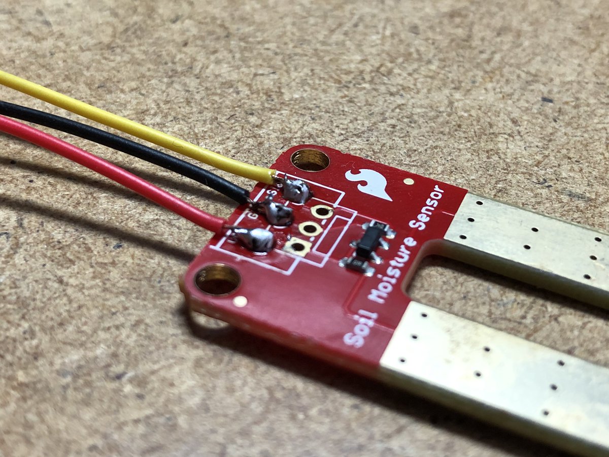
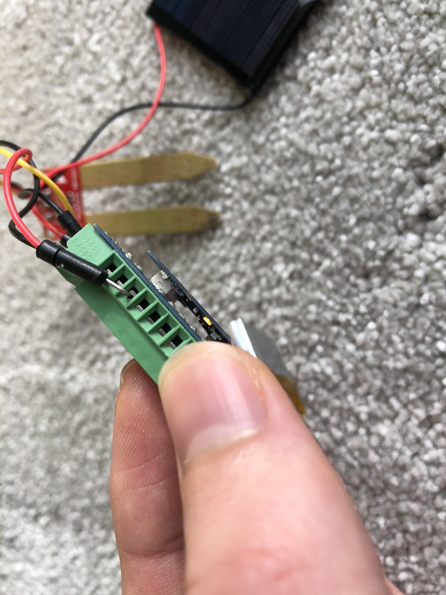
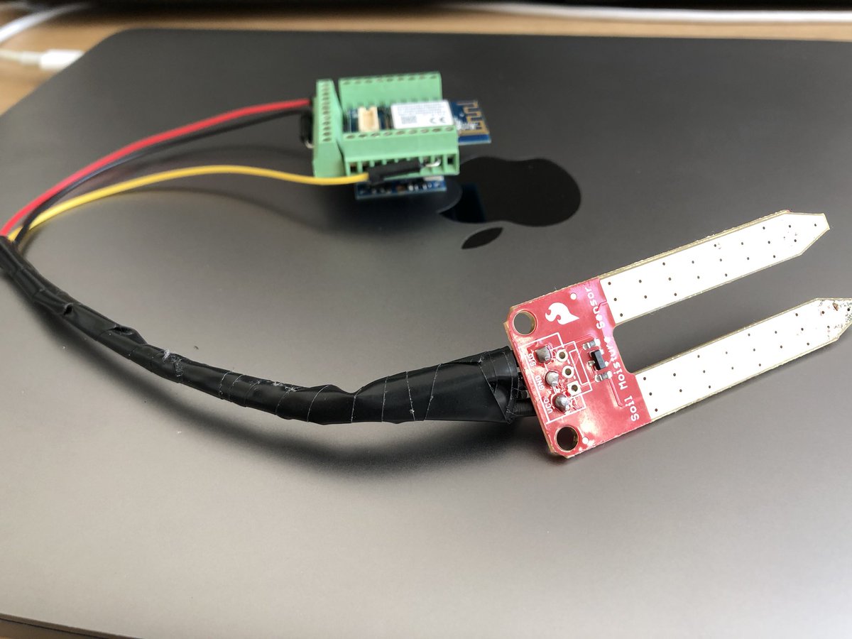
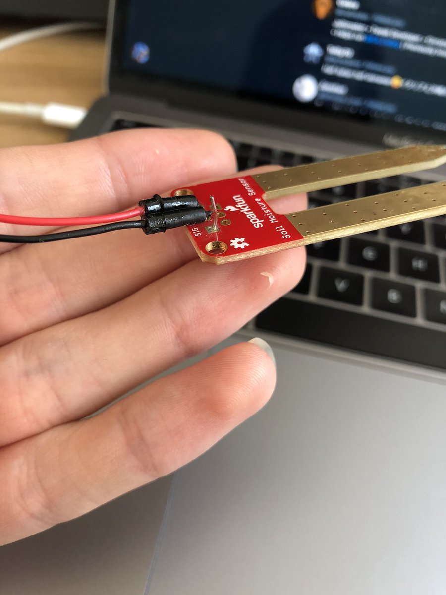
... and I broke it. Time to do some soldering  https://abs.twimg.com/emoji/v2/... draggable="false" alt="😂" title="Gesicht mit Freudentränen" aria-label="Emoji: Gesicht mit Freudentränen"> I did want to reduce cable length anyway
(I’ve also shortened the wires, and this also reduce the connection size to the sensor. So... by breaking it I guess I fixed other problems?)
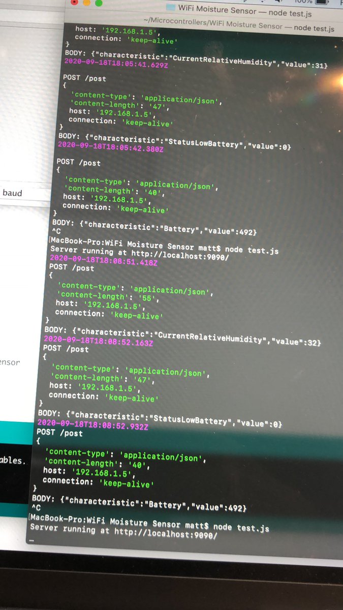
I’ve put together a sketch that sends a POST request every 5 mins (short time for debugging) to a local server, with the current soil moisture reading (plus battery voltage).
Now, I’ve started the first low power experiments to see what battery life to expect!
Now, I’ve started the first low power experiments to see what battery life to expect!
Would love to get a multimeter setup here to check current draw, but have zero clue where to begin  https://abs.twimg.com/emoji/v2/... draggable="false" alt="😅" title="Lächelndes Gesicht mit offenem Mund und Angstschweiß" aria-label="Emoji: Lächelndes Gesicht mit offenem Mund und Angstschweiß">
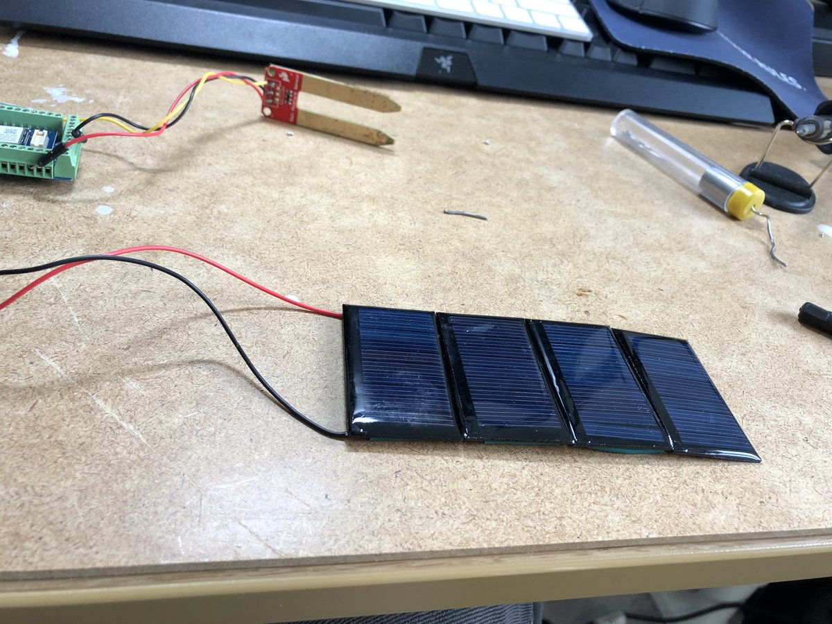
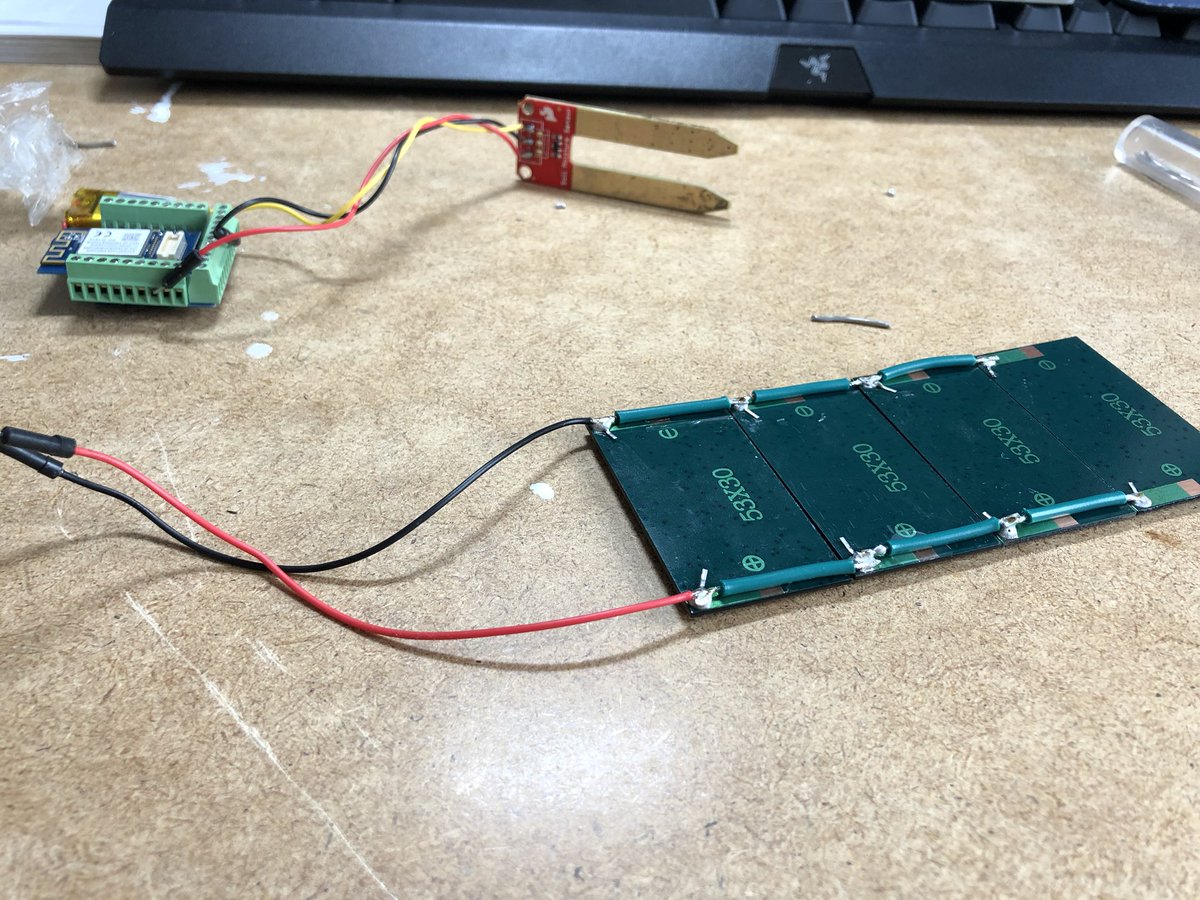
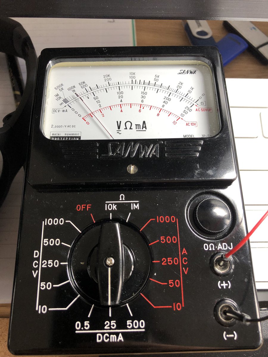
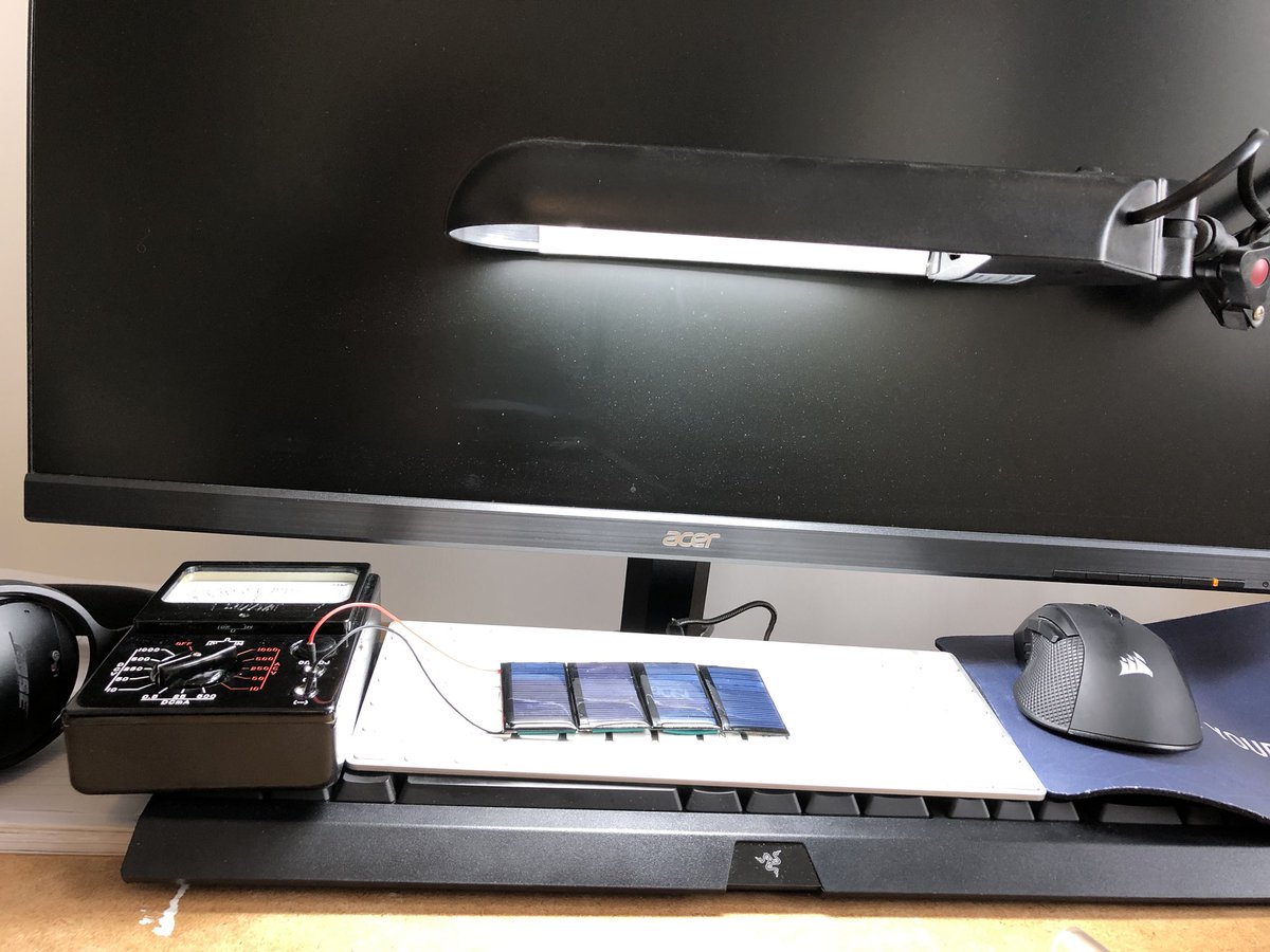
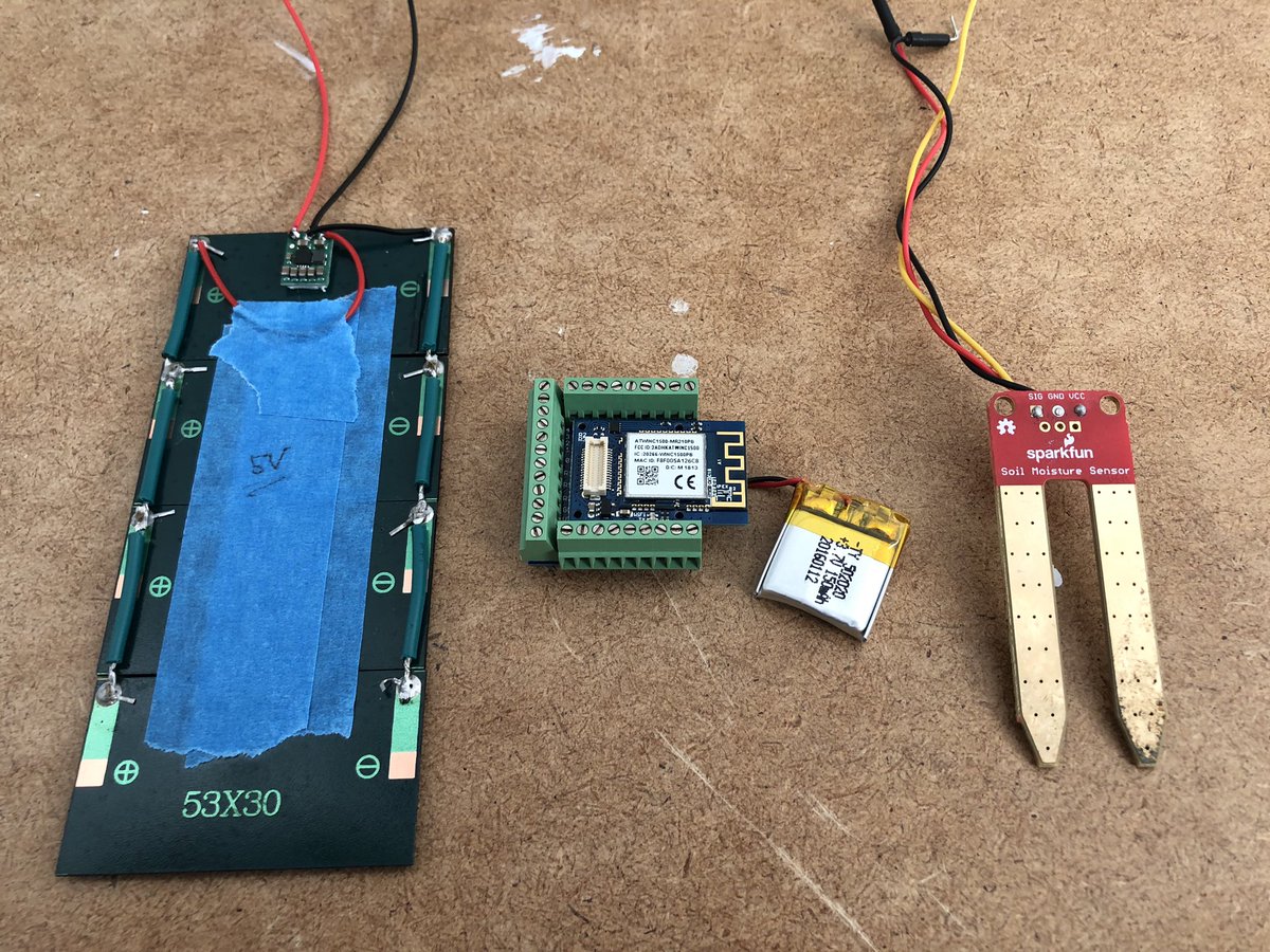
Soldered up some solar panels (5V in parallel) to keep this project running as long as possible. I’m seeing fairly good results from my test bench setup:
- ~4.2V DC
- 25mA
When shining artificial light directly on the panels, I get > 100mA, enough to charge my battery :)
- ~4.2V DC
- 25mA
When shining artificial light directly on the panels, I get > 100mA, enough to charge my battery :)
At this point, I just need to tweak my sensor calibration, and then it’s ready for a proper test over a day or two
Charging light is on at the location this project will be installed, so, I guess this is successful :)
Done some actual science™, and I’ve noticed that the output voltage varies wildly between 2.5v and 5.5v. This means either there’s not enough voltage to start charging the battery, or it could be too high and risk damaging my board.
So, just ordered a 5V buck-boost converter
So, just ordered a 5V buck-boost converter
This one specifically: https://www.pololu.com/product/2119
Here’s">https://www.pololu.com/product/2... to hoping my research is right https://abs.twimg.com/emoji/v2/... draggable="false" alt="😂" title="Gesicht mit Freudentränen" aria-label="Emoji: Gesicht mit Freudentränen">
Here’s">https://www.pololu.com/product/2... to hoping my research is right
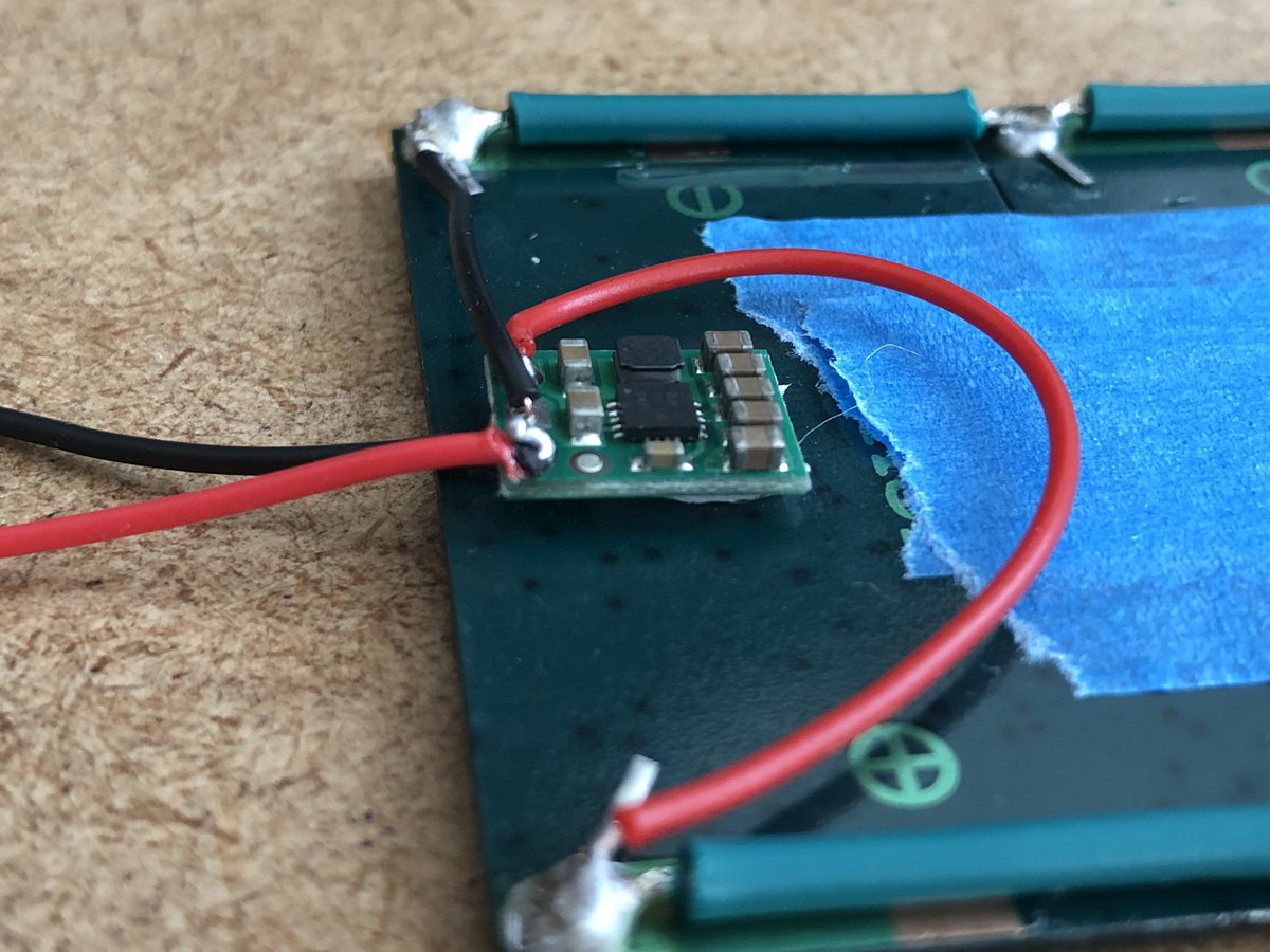
Regulator is installed. I’m seeing typically 5.2v (as stated in the datasheet) when directly connected to the multimeter, ~4.2v when connected to the tinyduino, but less than 4v in most lighting conditions when under load.
My guess is that my array simply does not output enough to supply 5V unless in intense sunlight. Adding more panels likely would solve this!

 Read on Twitter
 (normal sized mug for scale)" title="I can’t believe how small the TinyDuino is https://abs.twimg.com/emoji/v2/... draggable="false" alt="😳" title="Errötetes Gesicht" aria-label="Emoji: Errötetes Gesicht"> (normal sized mug for scale)">
 (normal sized mug for scale)" title="I can’t believe how small the TinyDuino is https://abs.twimg.com/emoji/v2/... draggable="false" alt="😳" title="Errötetes Gesicht" aria-label="Emoji: Errötetes Gesicht"> (normal sized mug for scale)">
 I did want to reduce cable length anyway" title="... and I broke it. Time to do some soldering https://abs.twimg.com/emoji/v2/... draggable="false" alt="😂" title="Gesicht mit Freudentränen" aria-label="Emoji: Gesicht mit Freudentränen"> I did want to reduce cable length anyway" class="img-responsive" style="max-width:100%;"/>
