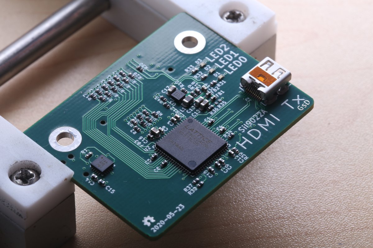
Just assembled a board, so you know what that means.
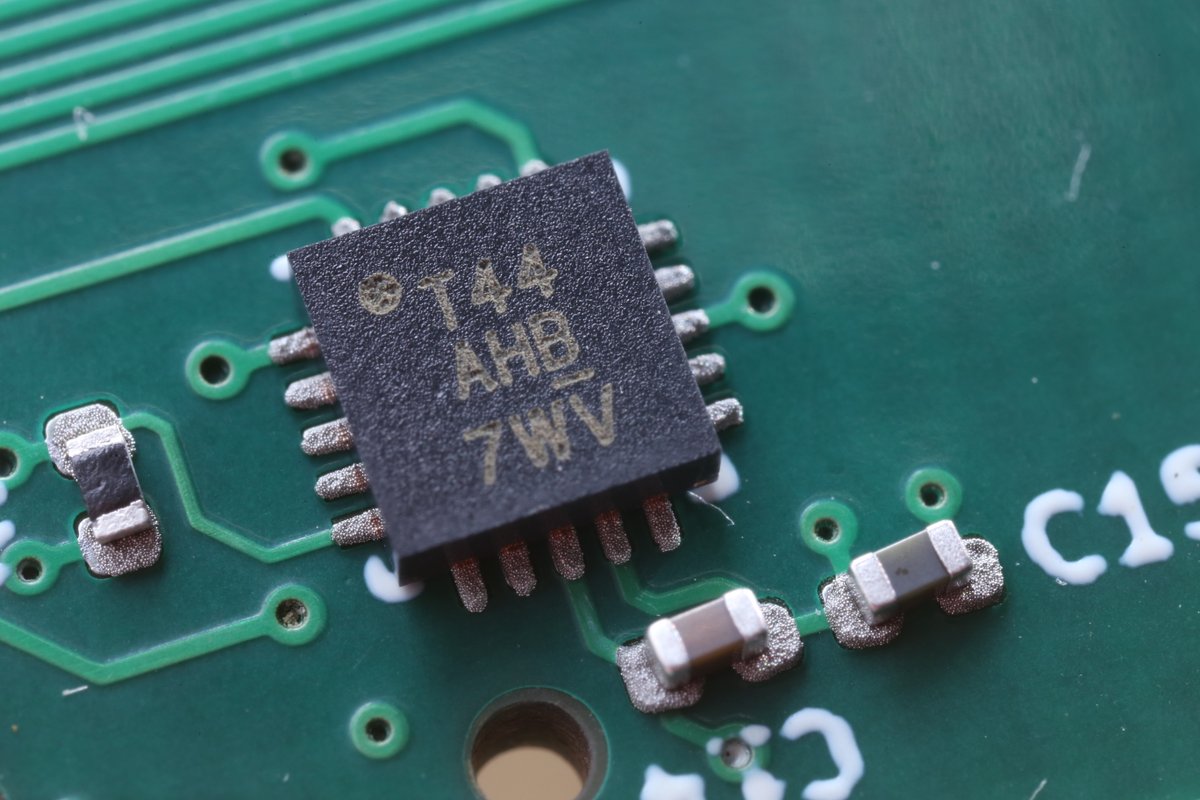
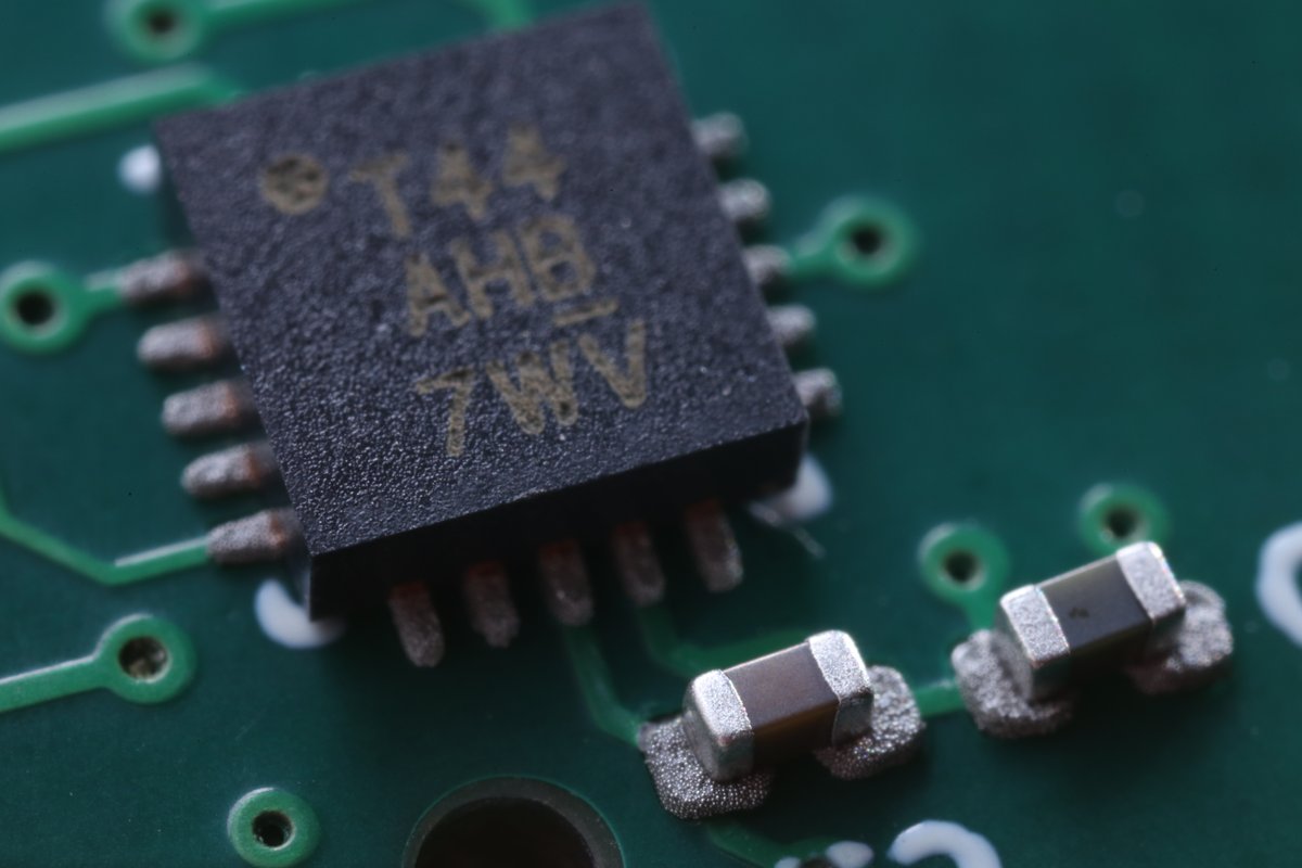
Macro photos!
 https://abs.twimg.com/emoji/v2/... draggable="false" alt="🧵" title="Thread" aria-label="Emoji: Thread">
Macro photos!
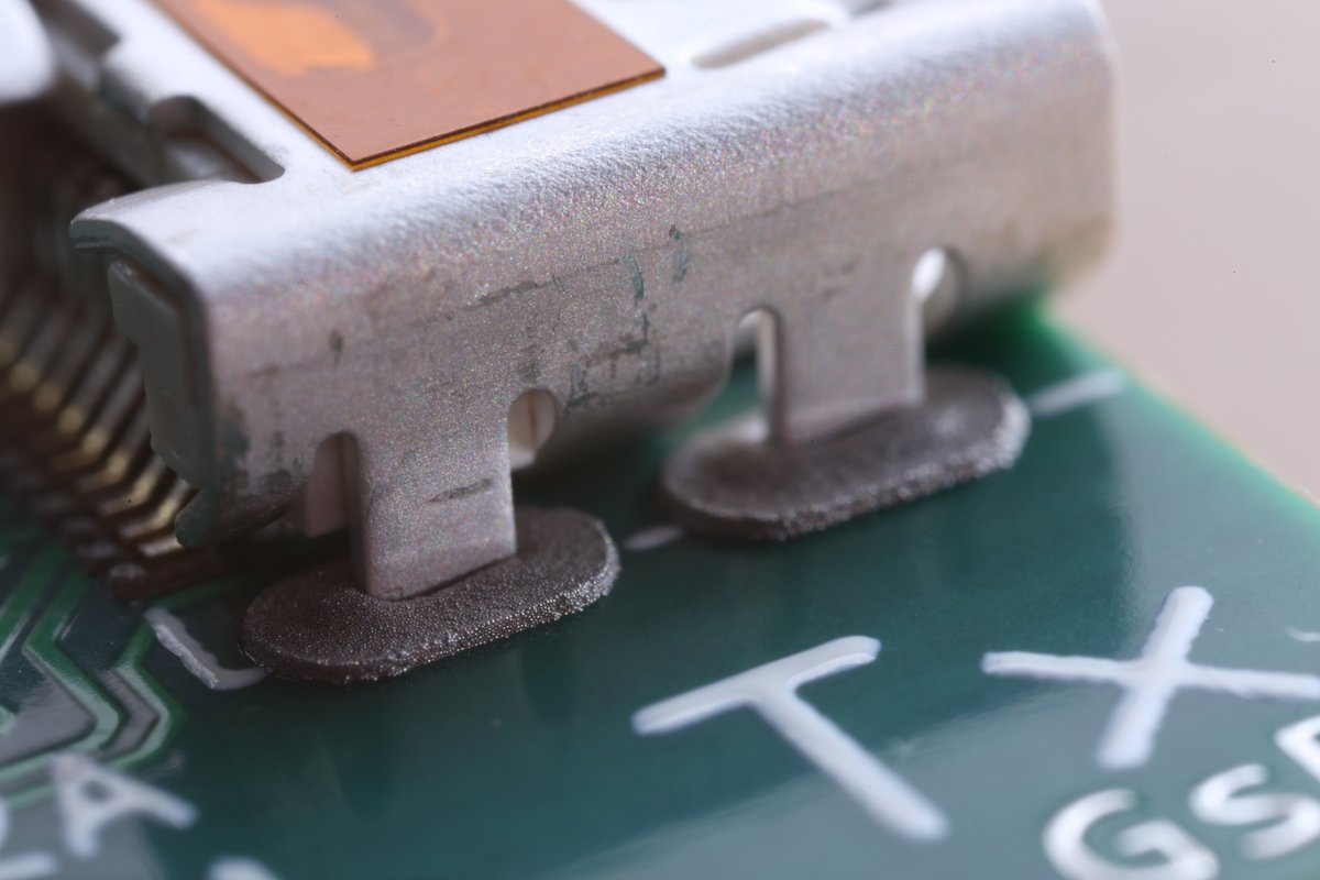
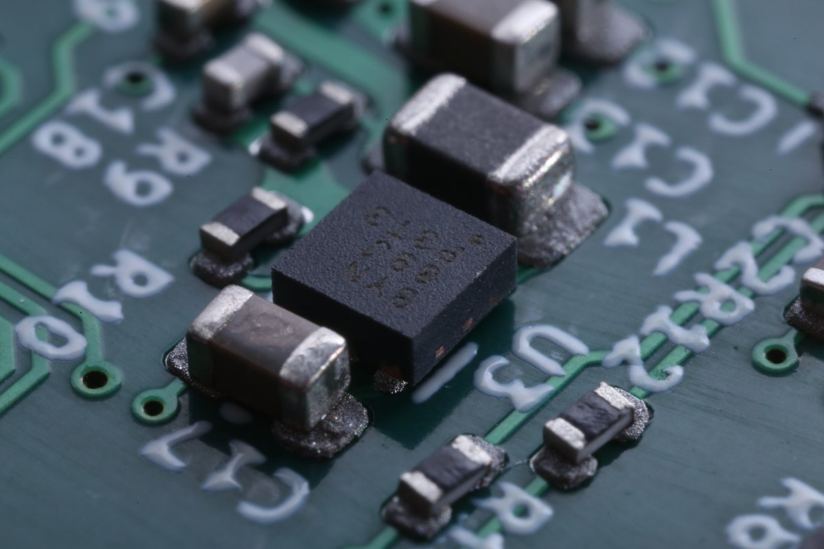
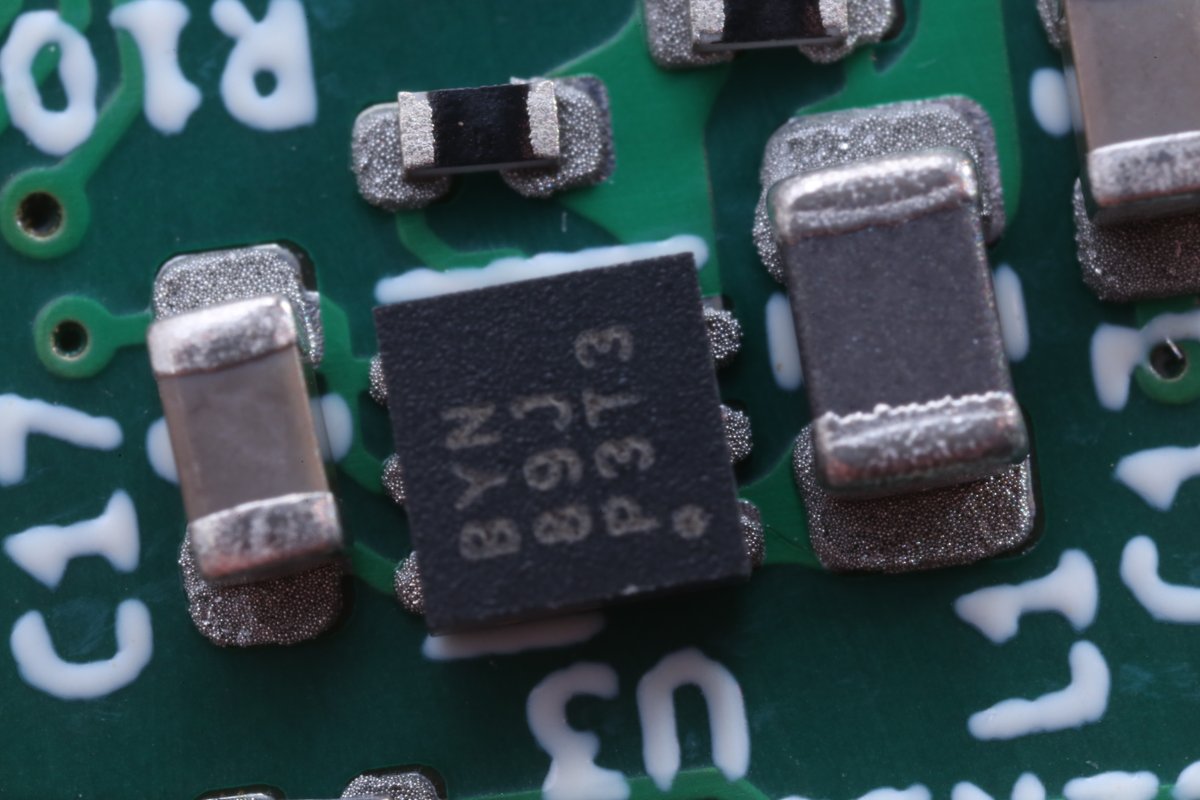
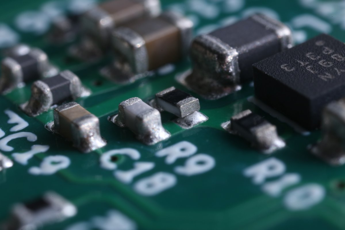
I& #39;m doing "Paste in Pad" here. The stencil has an opening, so the entire pad fills with paste.
Paste is made up from tiny spheres so it only fills ~75%. Even though this looks like a lot of solder, Once melted It& #39;s actually less than what I& #39;d apply hand soldering.
Paste is made up from tiny spheres so it only fills ~75%. Even though this looks like a lot of solder, Once melted It& #39;s actually less than what I& #39;d apply hand soldering.
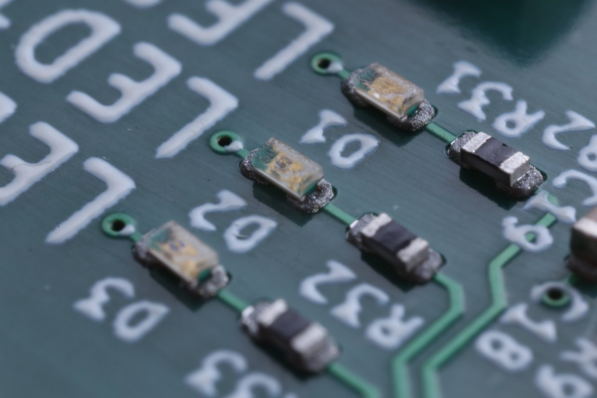
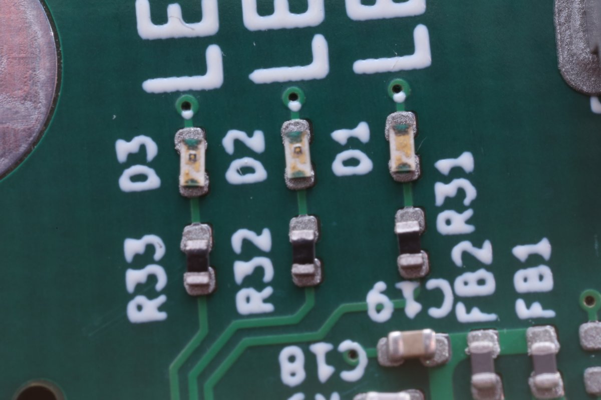
Using these 0402 LEDs for the first time. They look really neat. The lens basically covers the entire top, and the pads are underneath like a QFN package. It& #39;ll be interesting to see what they look like illuminated.
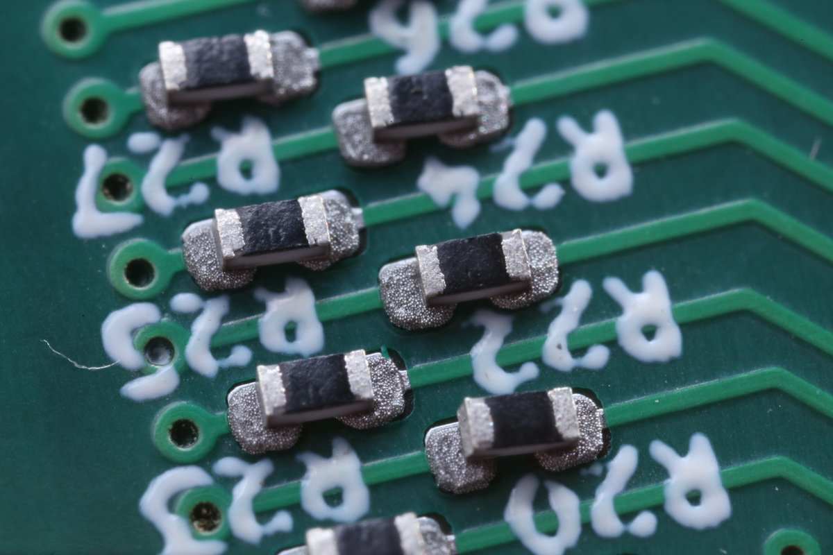
Inline 47R resistors. These reduce slew rate, so might help with reducing EMI.
But also they make good test points, and are easy to remove to add bodges if I got the design wrong. :>
But also they make good test points, and are easy to remove to add bodges if I got the design wrong. :>
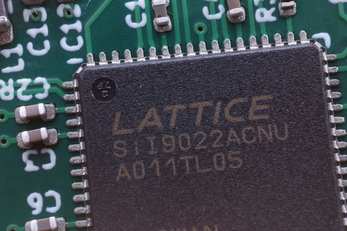
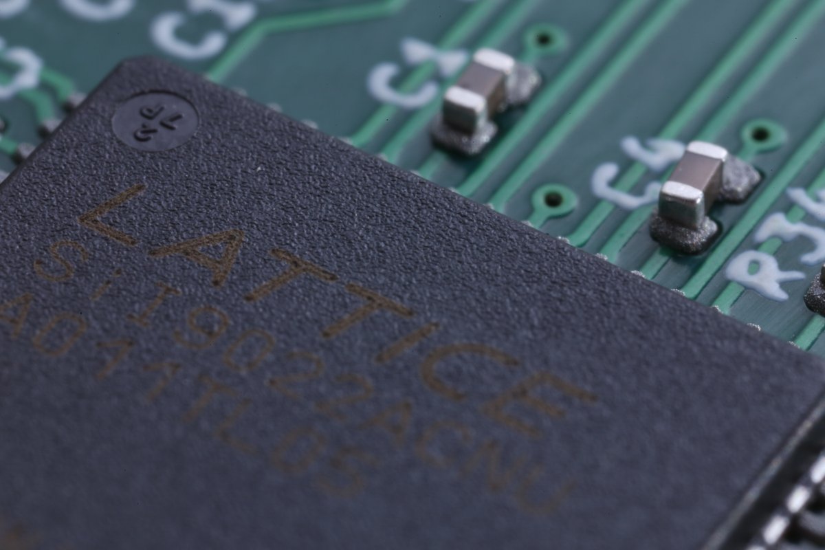
The main IC on this board is a Lattice SiI9022A. A HDMI transmitter. It& #39;s maybe obsolete, and the datasheet is maybe under NDA? (but LCSC still host it)
But it& #39;s still interesting to me because it supports audio over HDMI. Which the simpler DVI chips do not do.
But it& #39;s still interesting to me because it supports audio over HDMI. Which the simpler DVI chips do not do.
R.I.P.  https://abs.twimg.com/emoji/v2/... draggable="false" alt="🪦" title="Headstone" aria-label="Emoji: Headstone">

 Read on Twitter
 " title="Just assembled a board, so you know what that means. Macro photos! https://abs.twimg.com/emoji/v2/... draggable="false" alt="🧵" title="Thread" aria-label="Emoji: Thread">" class="img-responsive" style="max-width:100%;"/>
 " title="R.I.P. https://abs.twimg.com/emoji/v2/... draggable="false" alt="🪦" title="Headstone" aria-label="Emoji: Headstone">" class="img-responsive" style="max-width:100%;"/>


