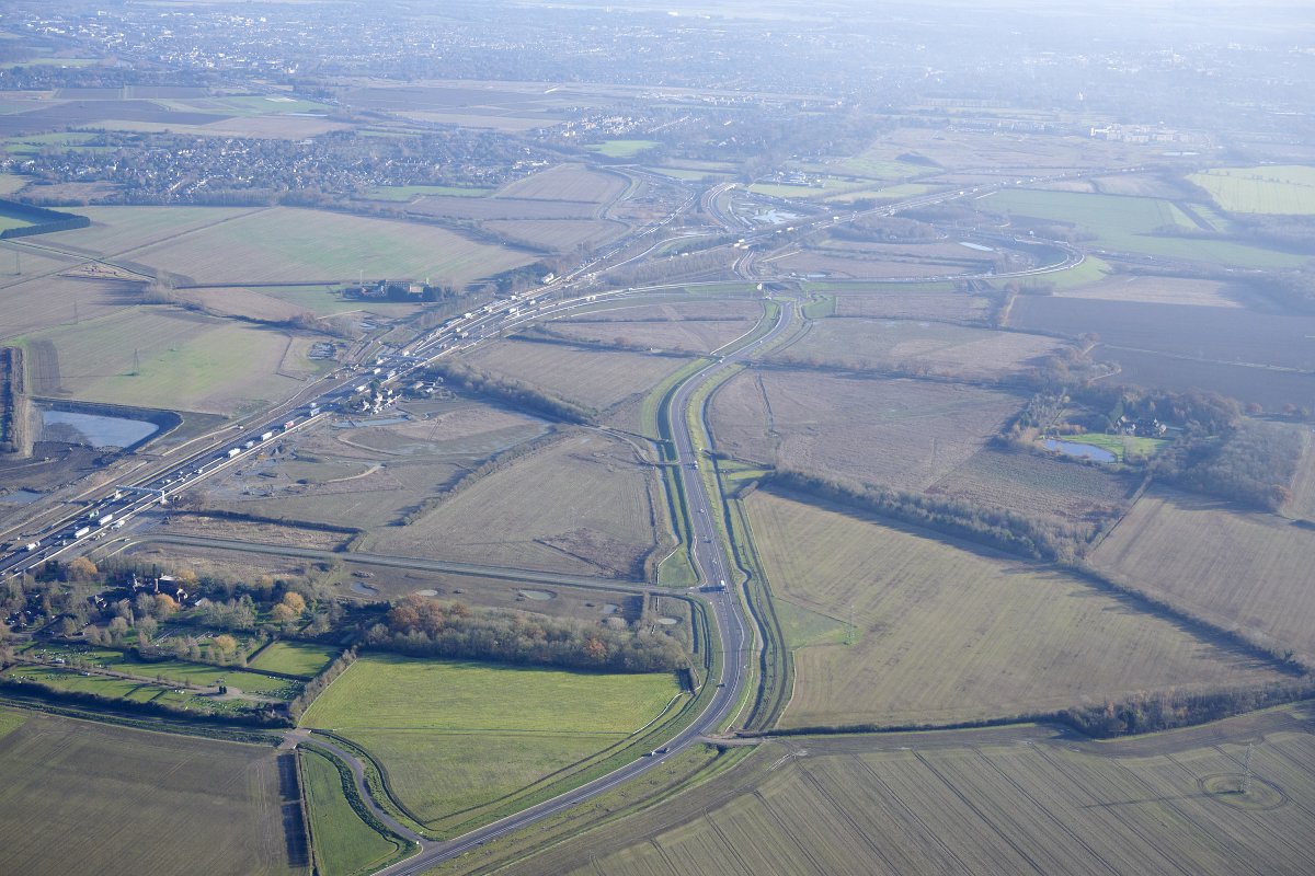
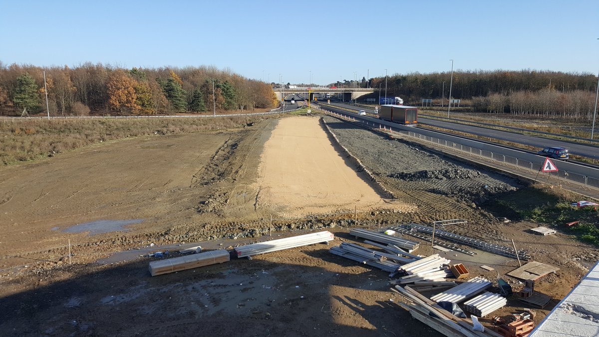
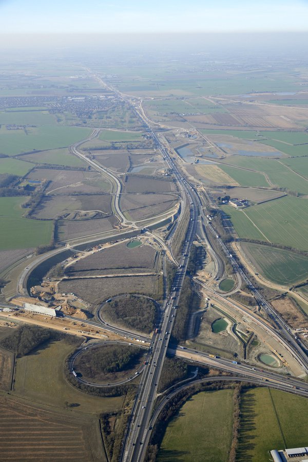
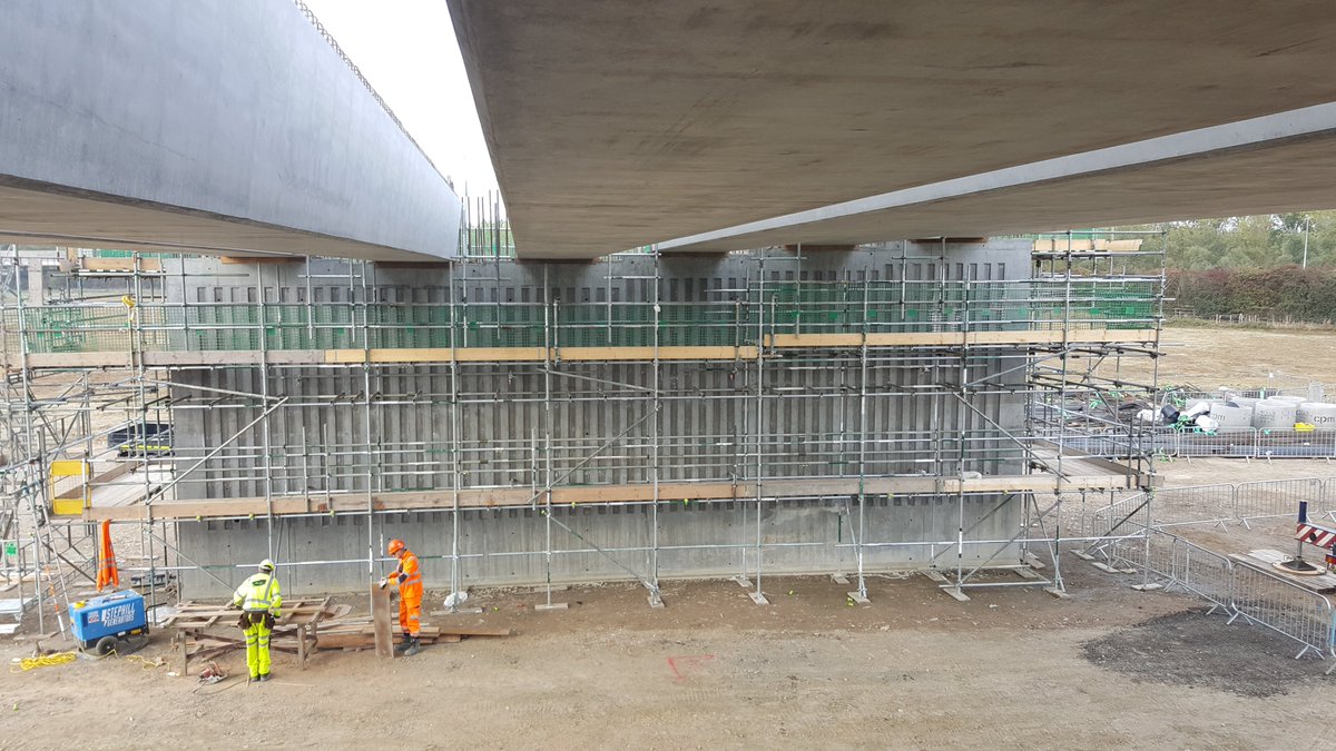
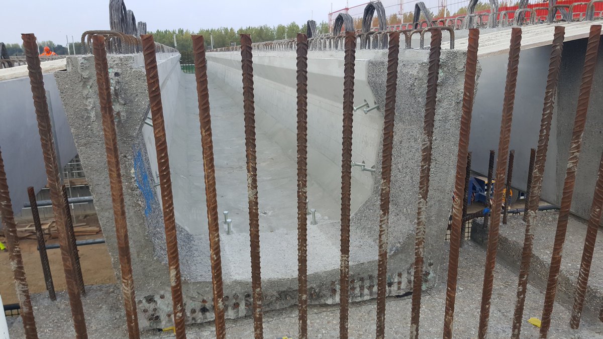
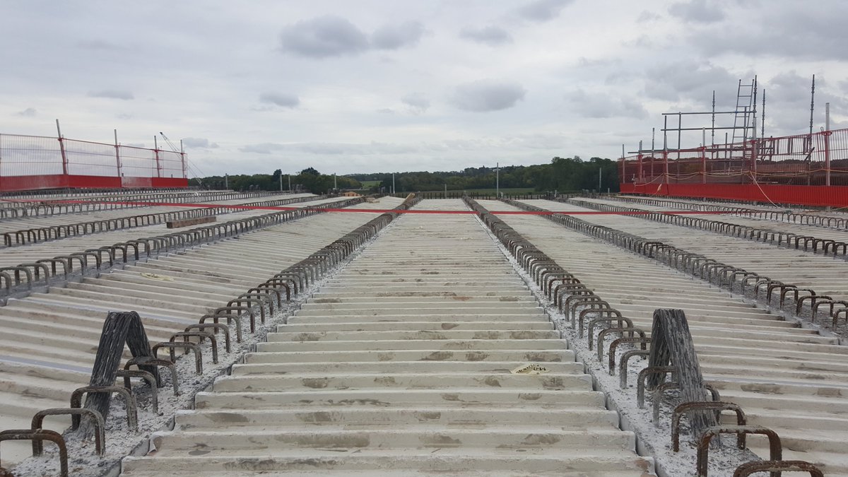
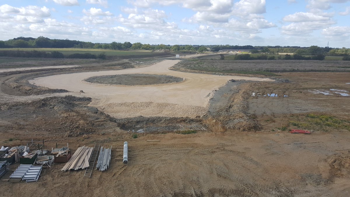
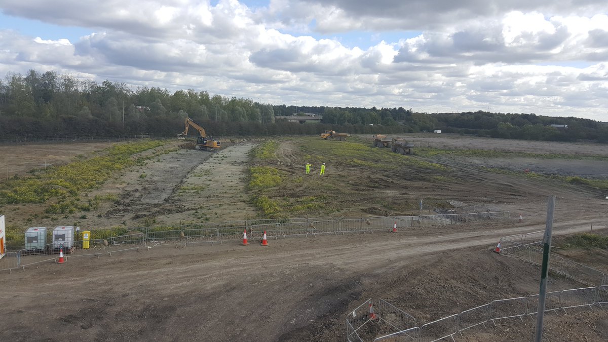
In honour of the A14 Cambridge to Huntingdon scheme fully opening yesterday, time for a behind-the-scenes look at some of the work at the A14/A428/M11 Girton Interchange and Bar Hill junction (image from @A14C2H ) 1/ #Construction #A14C2H #Engineering
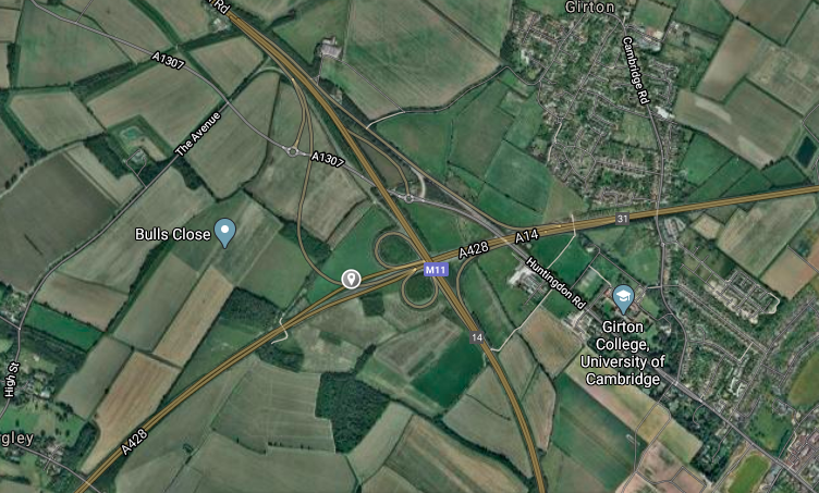
Girton Jct is where the A14, M11 and A428 meet. Traffic previously heading westbound on the A14 had to use a tight 270-degree loop which caused congestion; as part of the scheme a new link road was built (the orange line on the left of the jct) to be 2-lanes and faster-flowing 2/
Two structures on this westbound loop - BN25 carrying the new road over the A428 eastbound, and BN24 - carrying the loop over the new A1307 Local Access Road (LAR) 3/
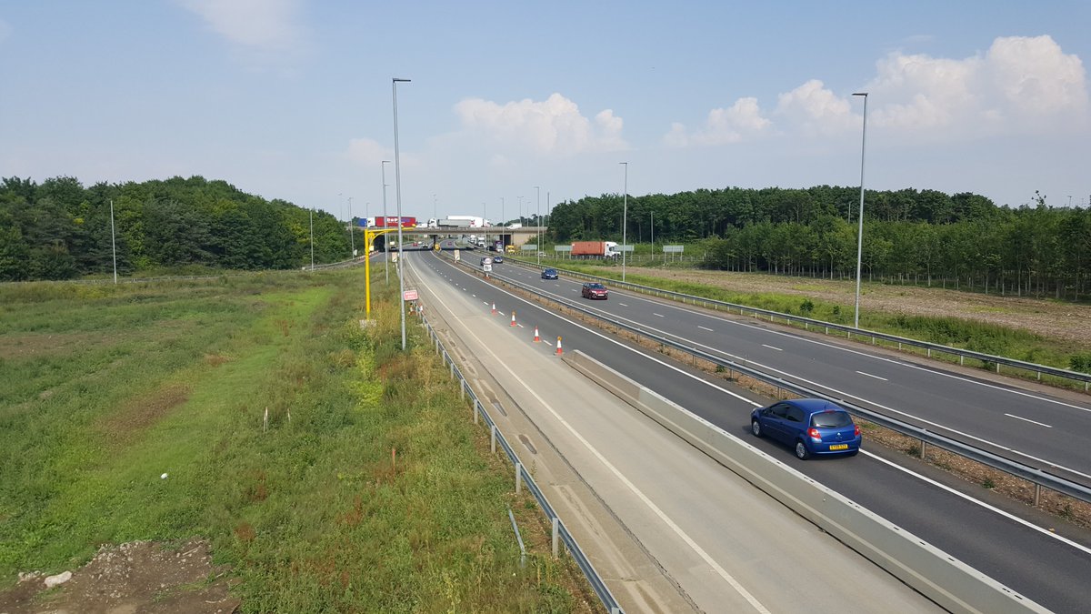
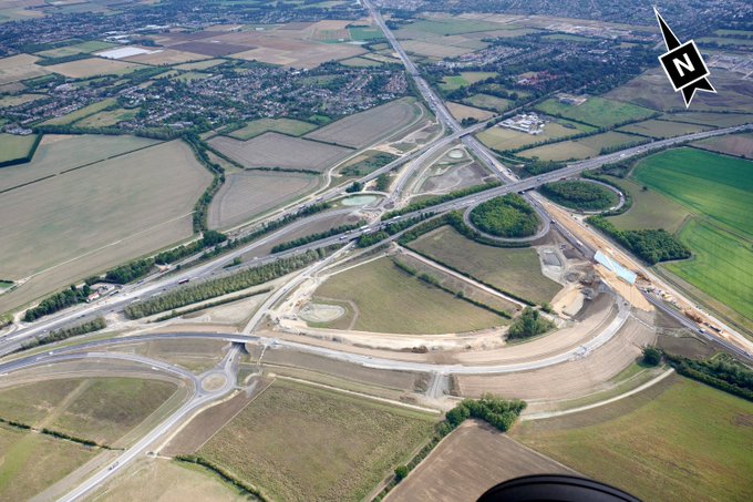
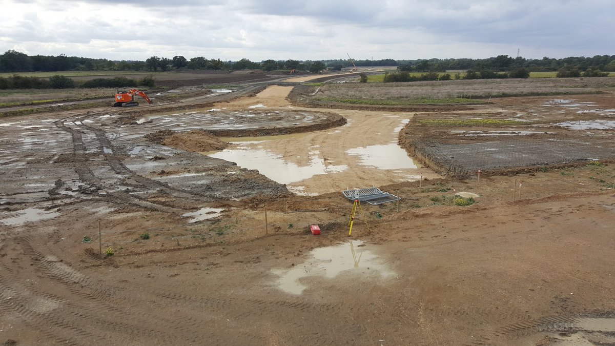
The photo below is from the BN25 location in June 2017 looking east - the A428 is on the right, the M11 overbridge in front (north is to the left - already stacked with traffic!) - the old 270-degree loop is visible on the far right with the red container lorry taking the turn 4/
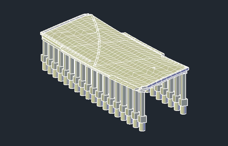
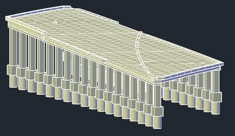
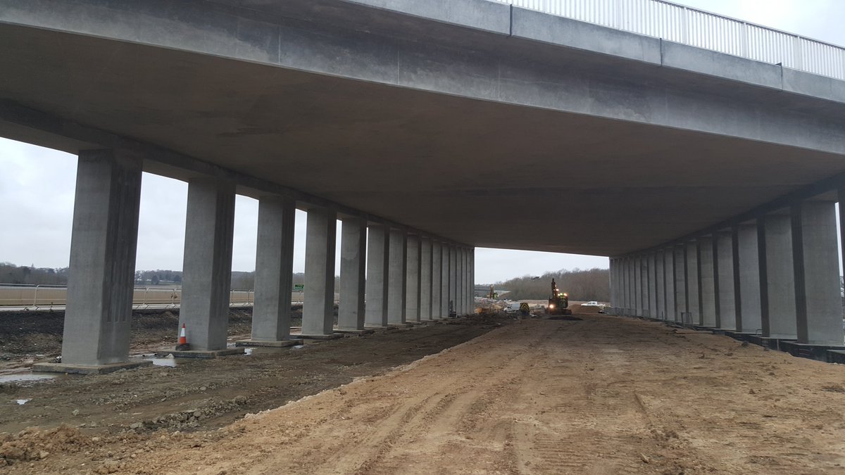
BN25 consisted of an in-situ integral slab supported on 36 individual columns, columns transfer to 1.8m diameter 30m deep reinforced concrete piles. The road took a sweeping bend here crossing the A428 at a very shallow angle hence the construction type 5/
3D model from another angle - we called it the & #39;ski jump& #39; as it rose by 4m and superelevation switched from a left-hand fall to right - partway across the deck. Total length 86m, 20m more and it& #39;s classed as a tunnel! The hardest bridge I& #39;ve ever set out 6/
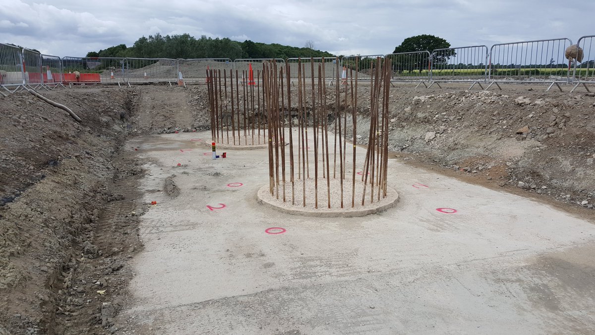
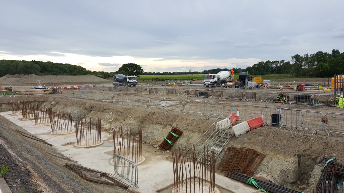
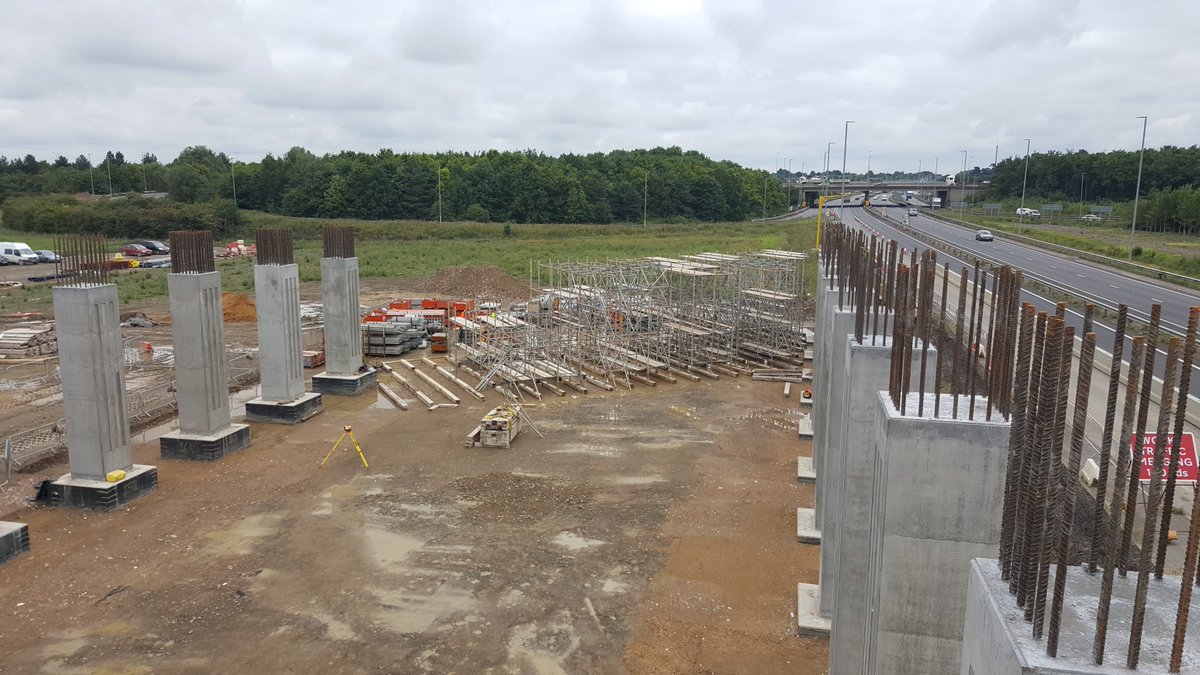
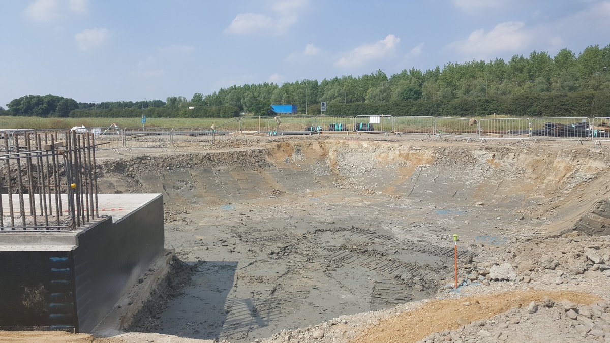
June 2017 - looking west - A428 on the right - here we see the tops of the piles (long concrete cyclinders going into the ground) - with steel reinforcing bar (rebar) sticking out - this is to provide a connection to the next part of the bridge 7/
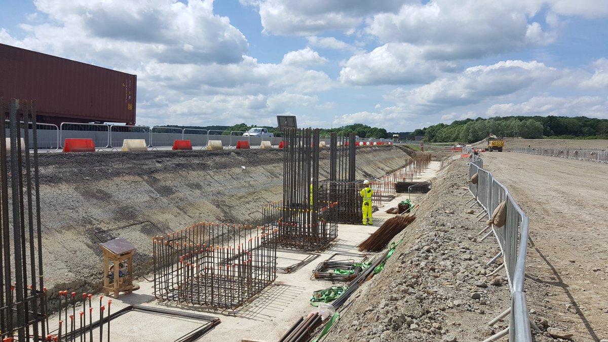
*Sorry A428 on the left on the previous photo. The excavation here approx 2m below ground level to allow the pilecaps to be built; pilecaps provide the connection between the piles (foundations) and the rest of the structure - normally link them together but here single caps 8/
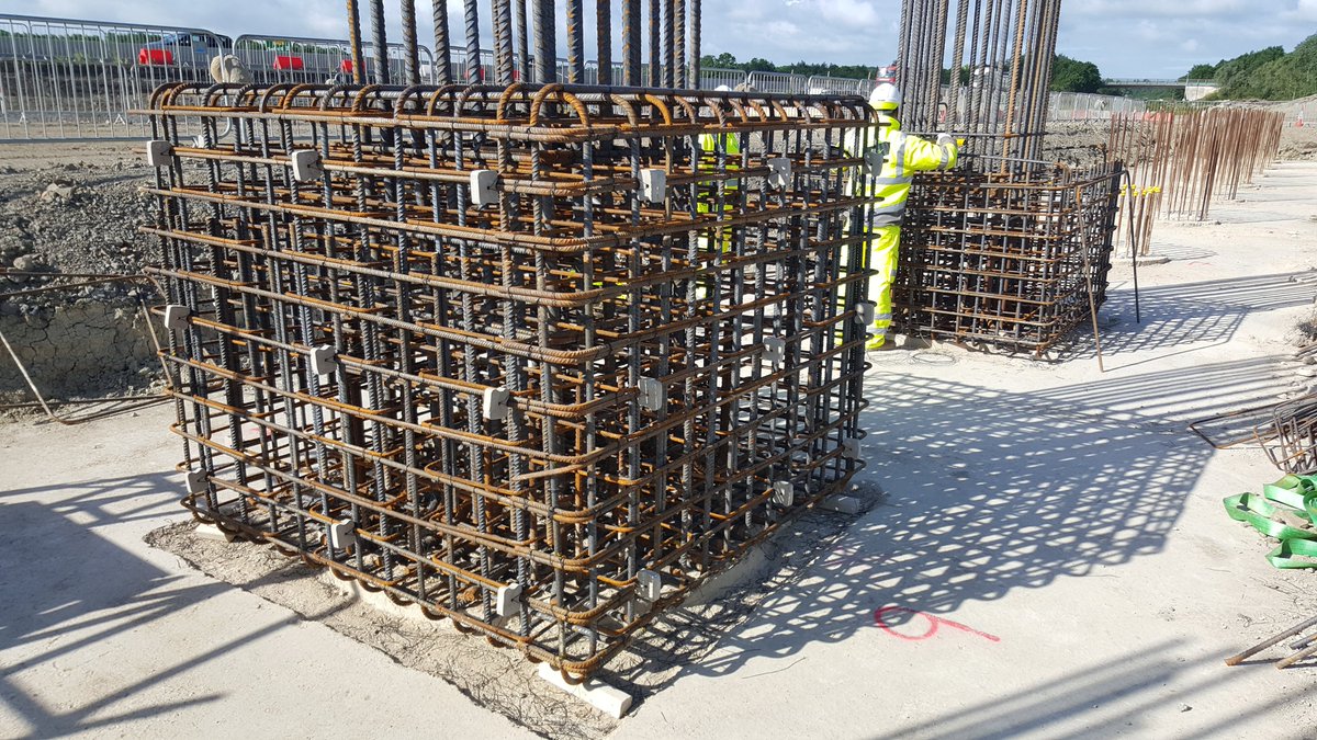
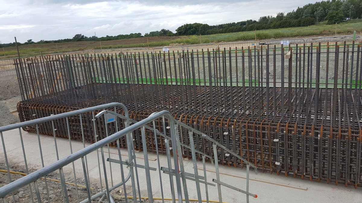
Here we see the rebar being fixed for the pilecaps; a cube of concrete which forms the base of the columns - the long tall bars are the starter bars for the columns which connect the column to the pilecap - it& #39;s all about good connections to ensure a stable structure! 9/
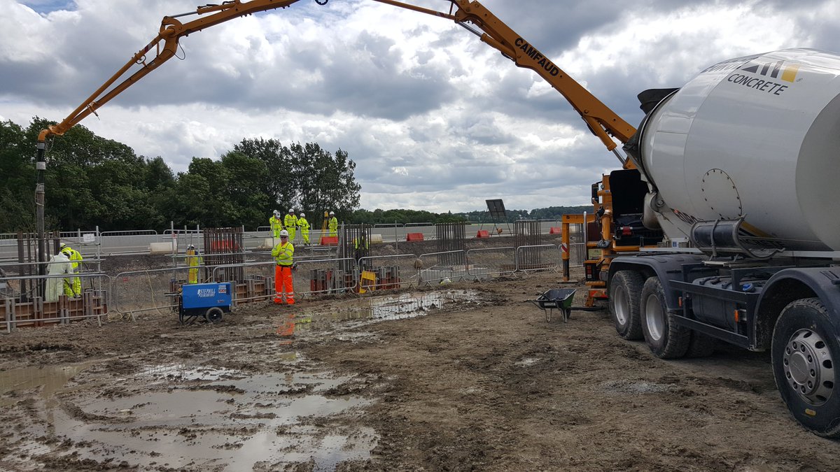
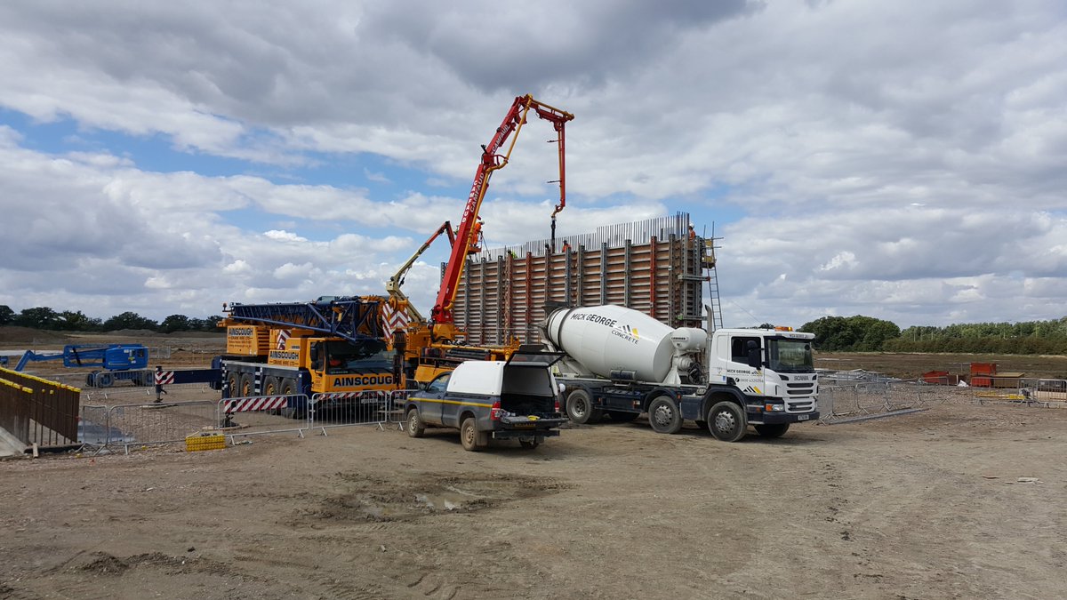
The rebar is fixed and then the concrete goes in! We were pouring two of these day with a little production line going, one team fixing, the next shuttering, then pouring, striking & moving the shutters to the next cap 10/
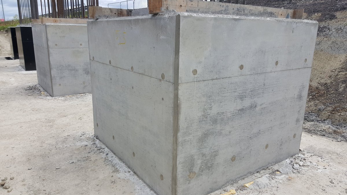
After curing (hardening of concrete) the shutters are struck, any minor defects are repaired - the small grey holes are where tie rods were used to bolts the shutters together to withstand the weight of the concrete, these are filled with mortar afterwards 11/
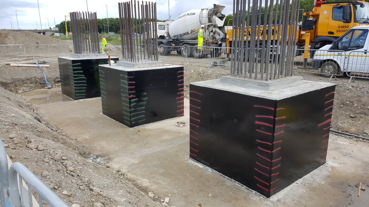
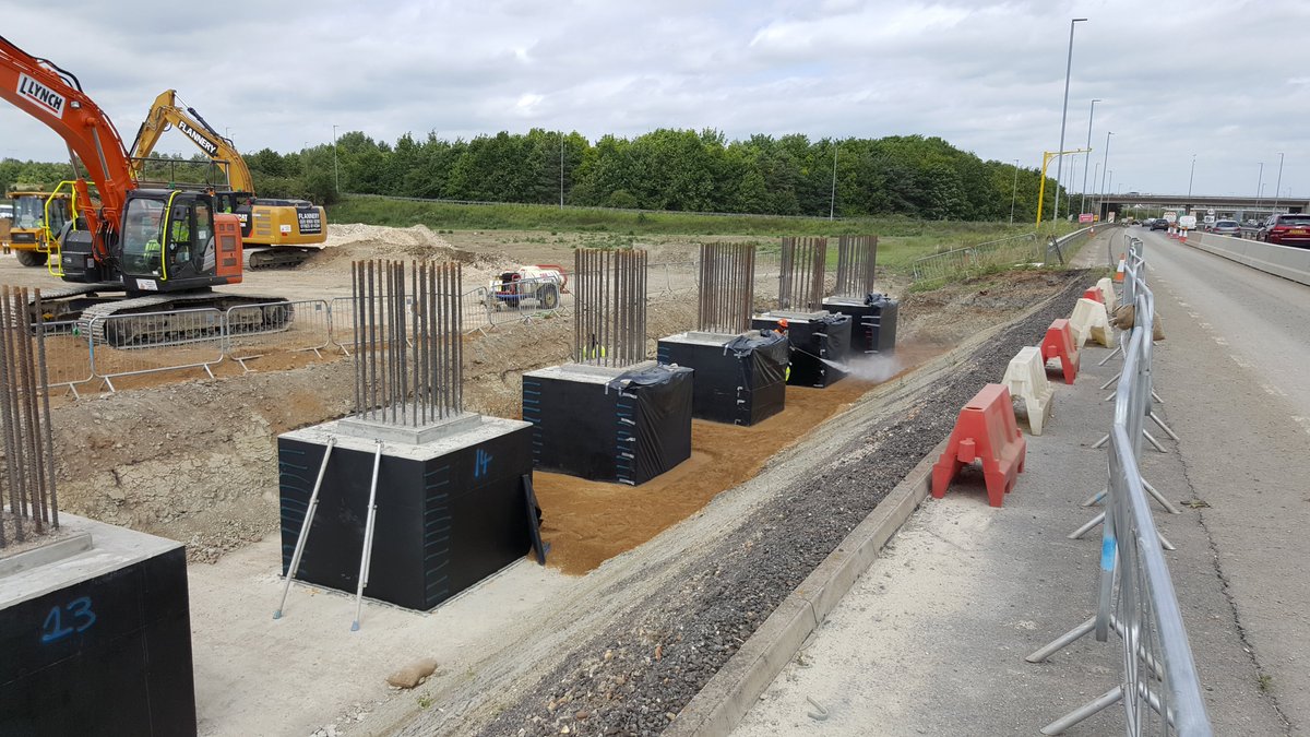
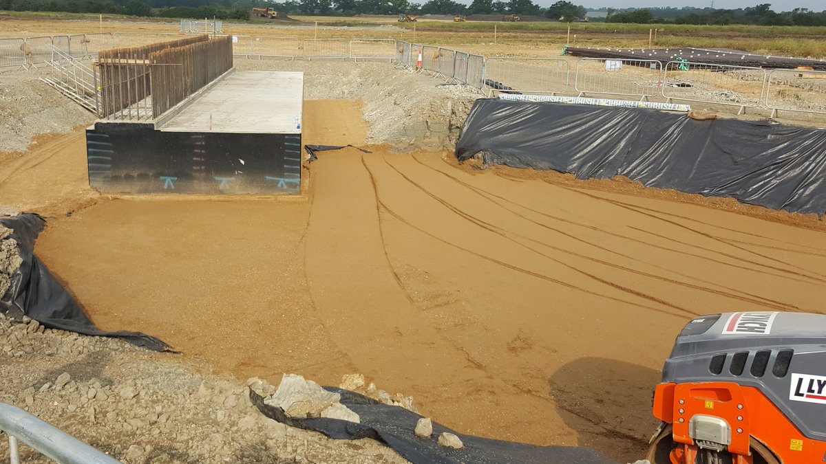
Then the pilecaps are painted with bitumen waterproofing paint; this prevents water ingress and corrosion by chemicals found in the soil. The caps are backfilled with structural fill in specified layers to avoid settlement, hence the coloured lines to ensure this is followed! 12/
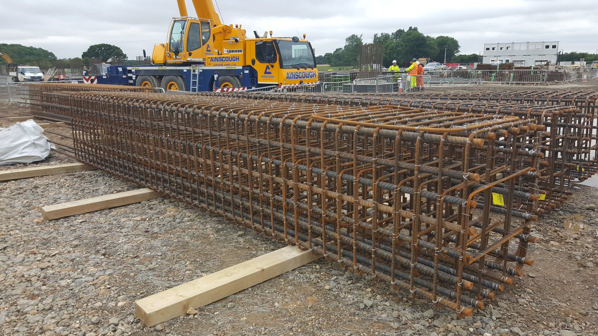
Whilst the pilecaps were being backfilled, the steel fixers were prefabricating the columns - this reduces working at height and allows two jobs to be done at once - it also makes them easier to inspect on the ground rather than up in the air! Heights ranged from 6m to 12m! 13/
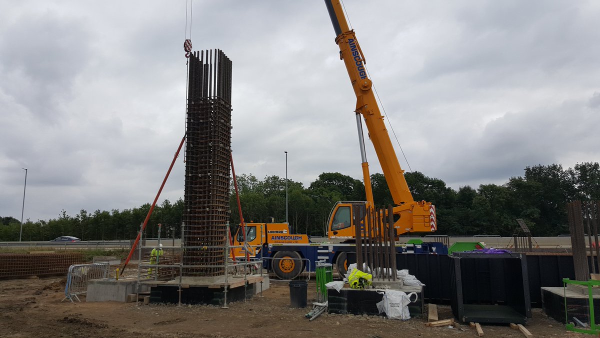
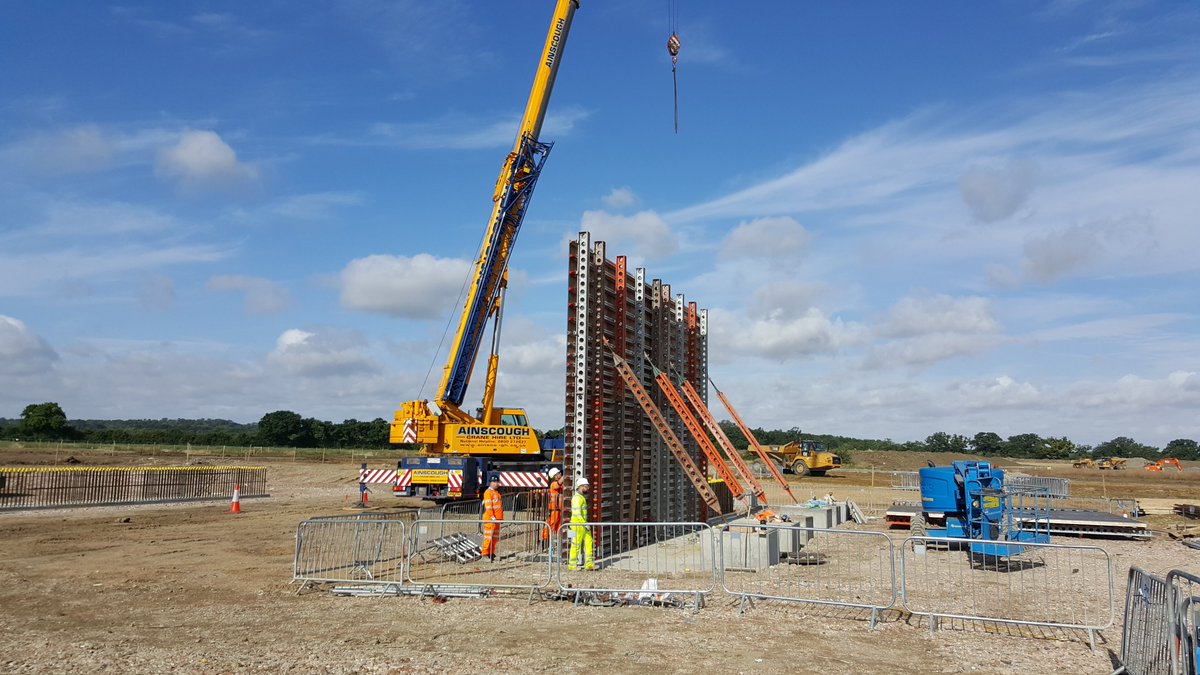
The column reinforcement is lifted into place and held by temporary props. The shutters (forms) for the concrete were made of metal so they could be reused for each column and specially fabricated in Germany 14/
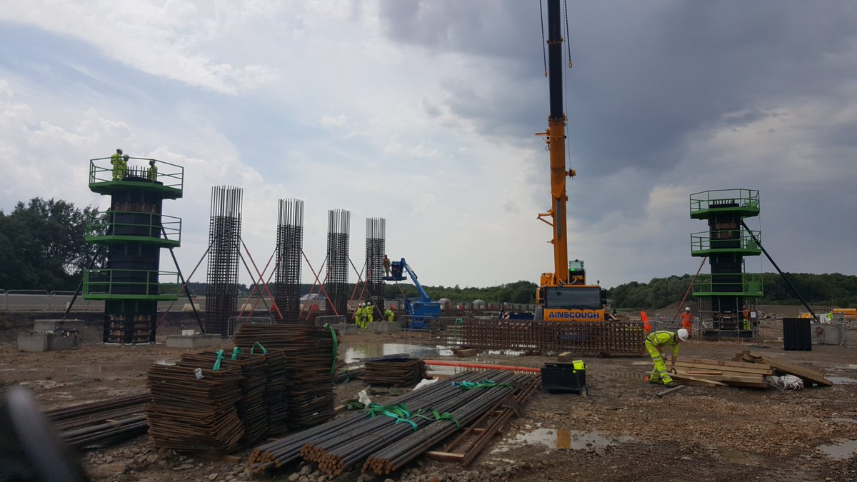
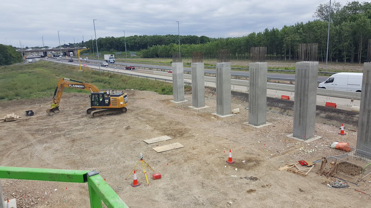
Here the first two columns have shuttering complete - green access platforms were to allow us to climb to the top to place the concrete - the bars sticking out at the top are (like the pilecaps) starter bars to connect the column to the deck 15/
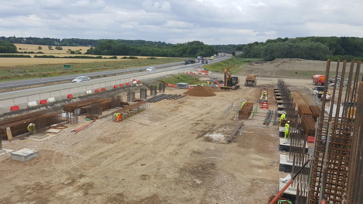
I& #39;ll be honest I quite enjoyed going up the columns as they gave great views across our part of the construction site! Remember the A14 C2H scheme was 21 miles so this is a small part of a massive project! Pic 1 looking west to M11, Pic 2 east along A428 towards St Neots 16/
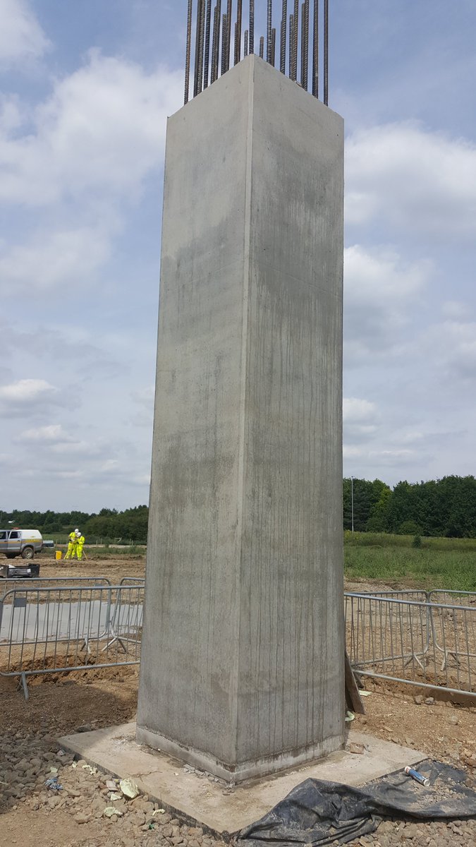
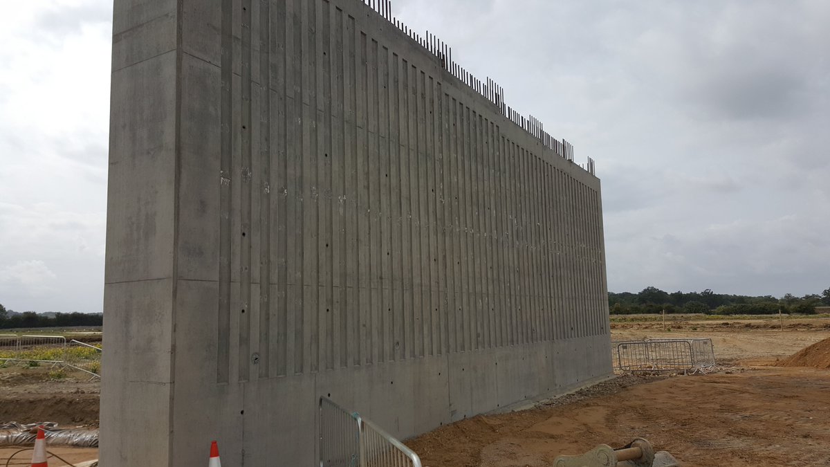
Close-up of a finished column - these are the rear faces but the front (internal) faces had feature grooves to discourage graffitti - the streaks on the concrete is the mould release oil, this was cleaned afterwards 17/
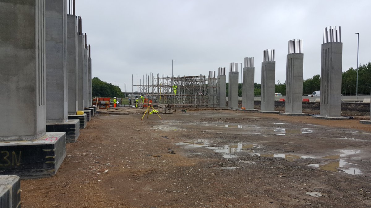
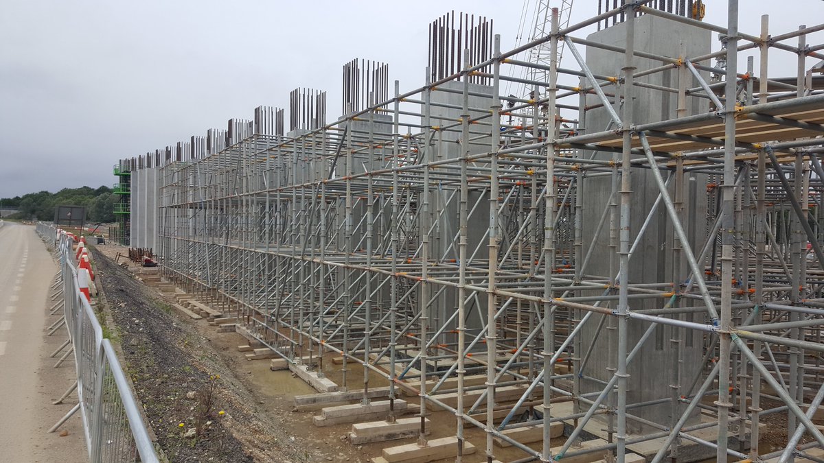
Once the columns were complete we turn to the deck. As the slab is in-situ (i.e. built in-place) we had to construct a falsework (temporary soffit) to build the deck from and support the rebar and concrete until it is self-supporting 18/
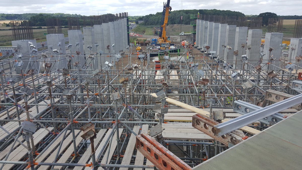
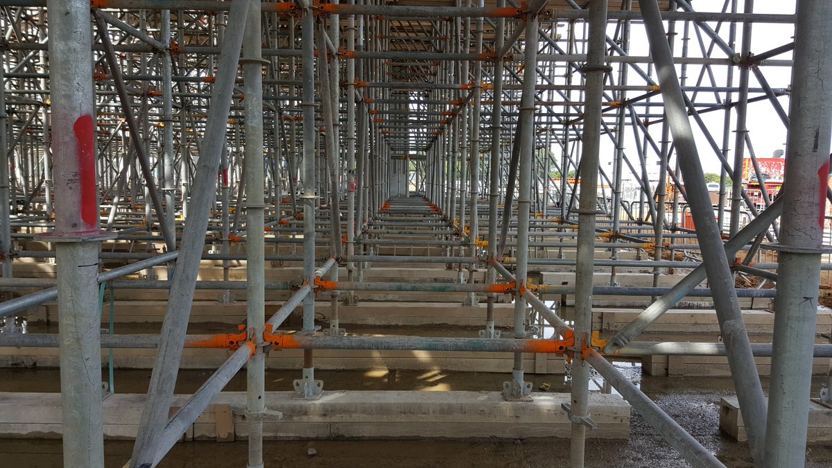
The falsework system is a proprietary type of scaffolding, with standards (vertical tubes) situated on timber sleepers, which sat on a specially-constructed stone mat - the tubes all clipped together and were adjustable to suit the falls of the bridge 19/
Building this falsework was a massive undertaking and we had around 50 operatives full-time just on this bridge. At the top of the standards was a u-head bracket whcih held the support beams - faced with marine plywood for a smooth finish to the deck soffit 20/
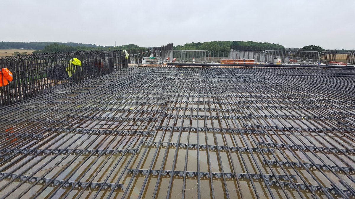
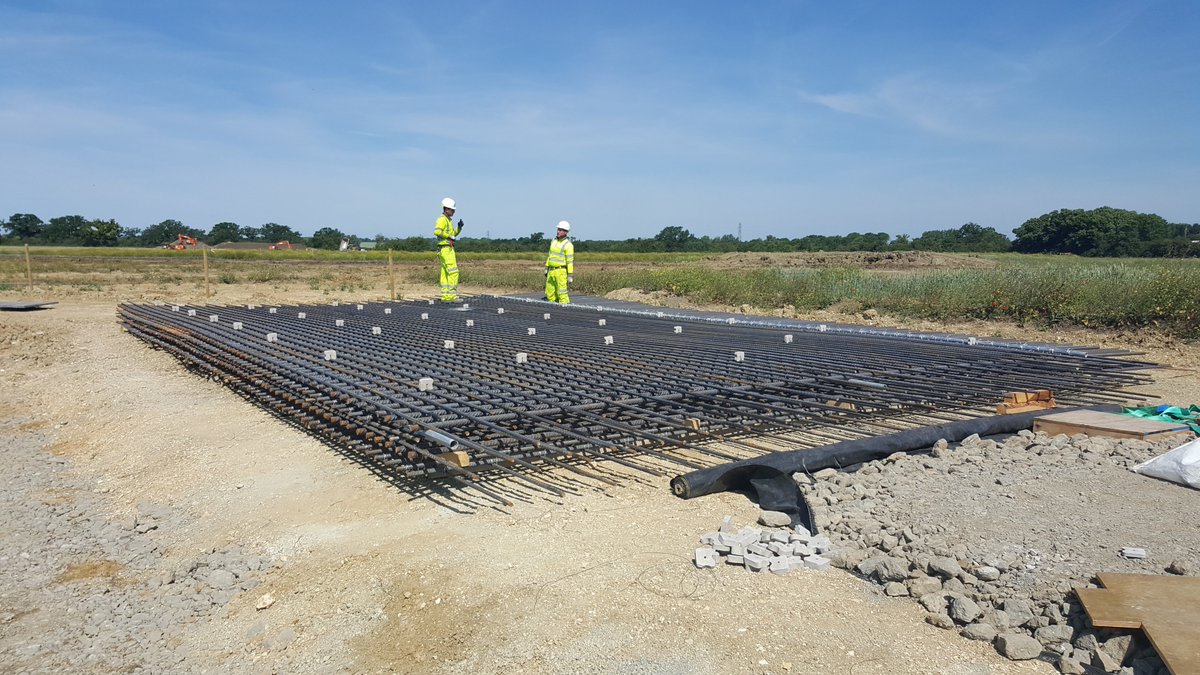
Rebar fixing for the deck bottom mat in August 2017; here the bottom layer of rebar has been fixed, on the left the sides are installed - the slab was between 1.2-1.5m thick! Plastic grey strips are spacers to keep the rebar off the wood & ensure good embedment into concrete 21/
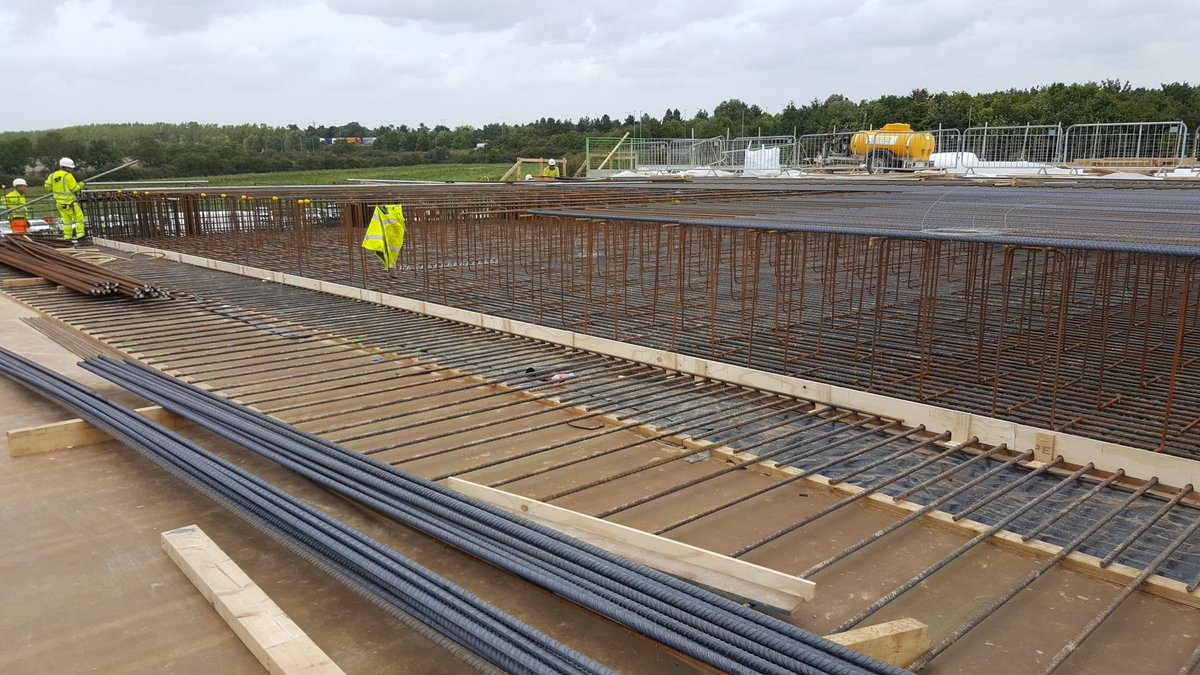
Another pic of the slab, now with the top mat fixed as well - the vertical bars supporting the top mat are all temporary (called chairs) and do nothing to strengthen the structure - they& #39;re purely to hold the top layer up. You can also see the crossfall of the deck well 22/
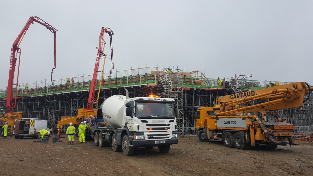
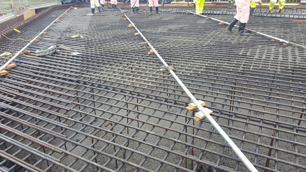
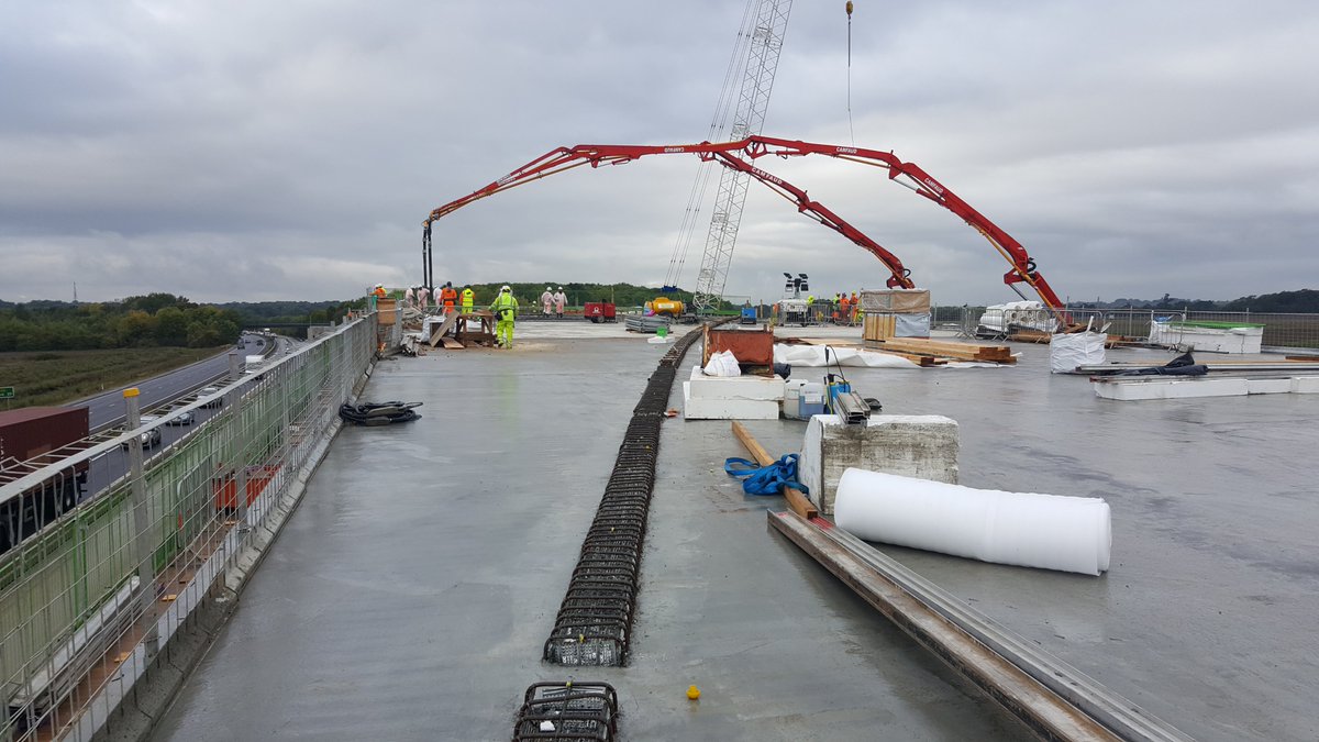
The deck was divided into 6 section for concrete pours, each section volume varying 250-600m3 - each pour used two concrete pumps + 1 standby, and was supplied from 4 concrete plants at Ellington, St Ives, Wood Green, & Cambridge 23/
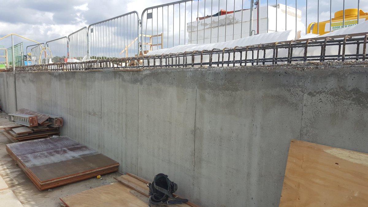
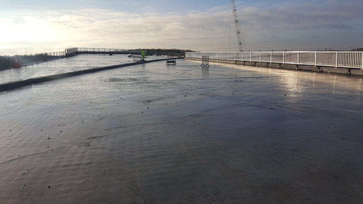
Once concrete had cured the shutters would be removed and next pour prepared. Pic 1 is top of deck slab looking towards Girton Jct, Pic 2 is a side-on pic of the deck slab showing how thick it is - the self-weight is enormous before you put 2 lanes of HGVs on top! 24/
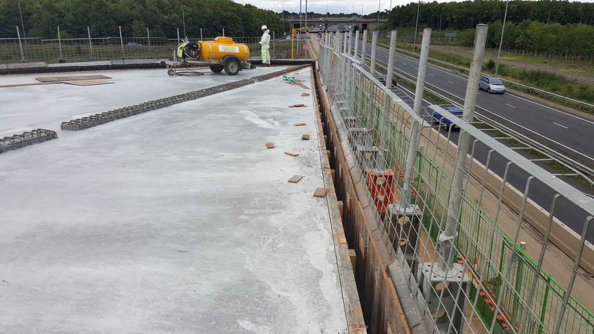
The line of rebar protruding here is a plinth for a vehicle restraint system (Crash barrier) to be installed - traffic will run on the left of this barrier so you can see how much unused space is on the right - this is for forward visibility for drivers round the bend 25/
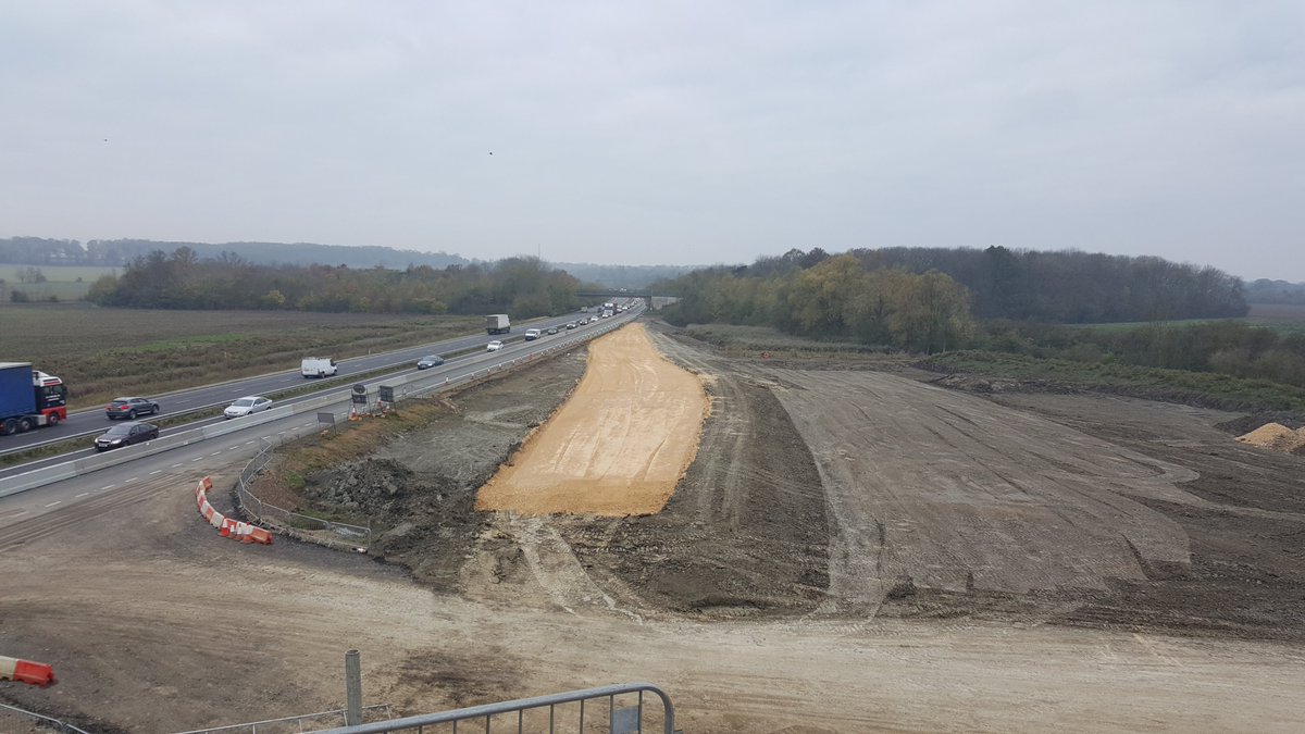
November 2017 and the roads team make a start on building the new A428 eastbound through the structure - Pic 1 looking west, pic 2 looking east at Girton jct, both from new bridge- the yellow stone is the foundation layer in the highway pavement construction known as sub-base 26/
January 2018 - the bridge is nearly finished and is waiting for the earthworks to catch up so the road can be built beneath and on top - this takes another 18 months until the westbound loop is open 27/
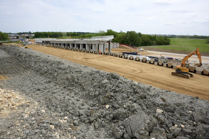
The approach embankments are made of reinforced earth - aggregate with metal straps layered on top of another, fixed to concrete panels that retain the fill - it holds itself together (photo from @A14C2H - you can really see the gradients here!) 28/
More photos pinched from @A14C2H as I do not own a plane - BN25 is big white blob bottom left on Pic 1, with the earthworks for new westbound link very defined - this embankment ran at approx 15m above ground level and the earth excavated locally from a "borrow pit" 29/
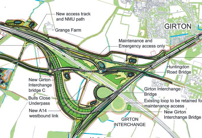
Here& #39;s an extract of the plans for Girton Junction to help tie it all together 30/
The bridge is not a common type but other examples exist in the UK such as the A46 west of the M40, and a raft of these are to be built for HS2 on the M42 and M6 around Birmingham.
Part 2 for the A1307 bridge, and Bar Hill & Swavesey junctions to follow later this week 31/.....
Part 2 for the A1307 bridge, and Bar Hill & Swavesey junctions to follow later this week 31/.....
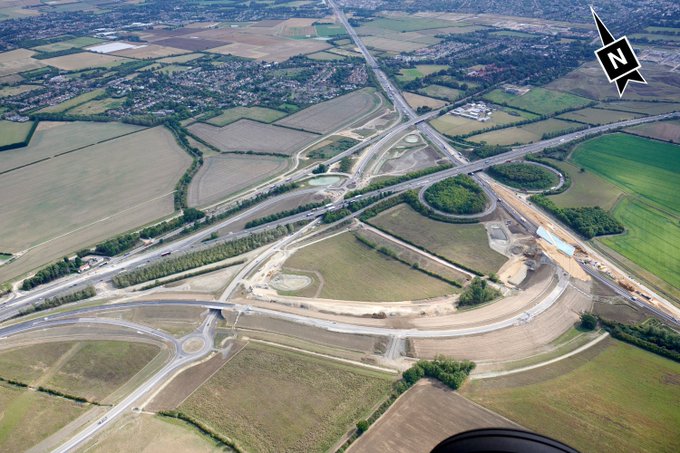
PART 2 - BN24 - A14/A1307 Girton Overbridge as seen in bottom left of this aerial pic taken from @A14C2H /32
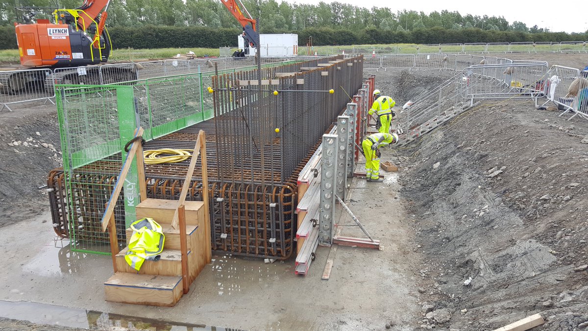
This bridge has similar principles to BN25 - foundations are two rows of 30m deep reinforced concrete piles tied together with a pile cap - this is the reinforcement for the pile cap which spreads the loads over the piles /33
There are two abutments (walls) to the bridge - the shutters to the pilecaps are built once rebar complete. The shutters act as the mould for the concrete until the concrete cures. Long straight bars are starter bars for the abutment wall (good connections as mentioned for BN25)
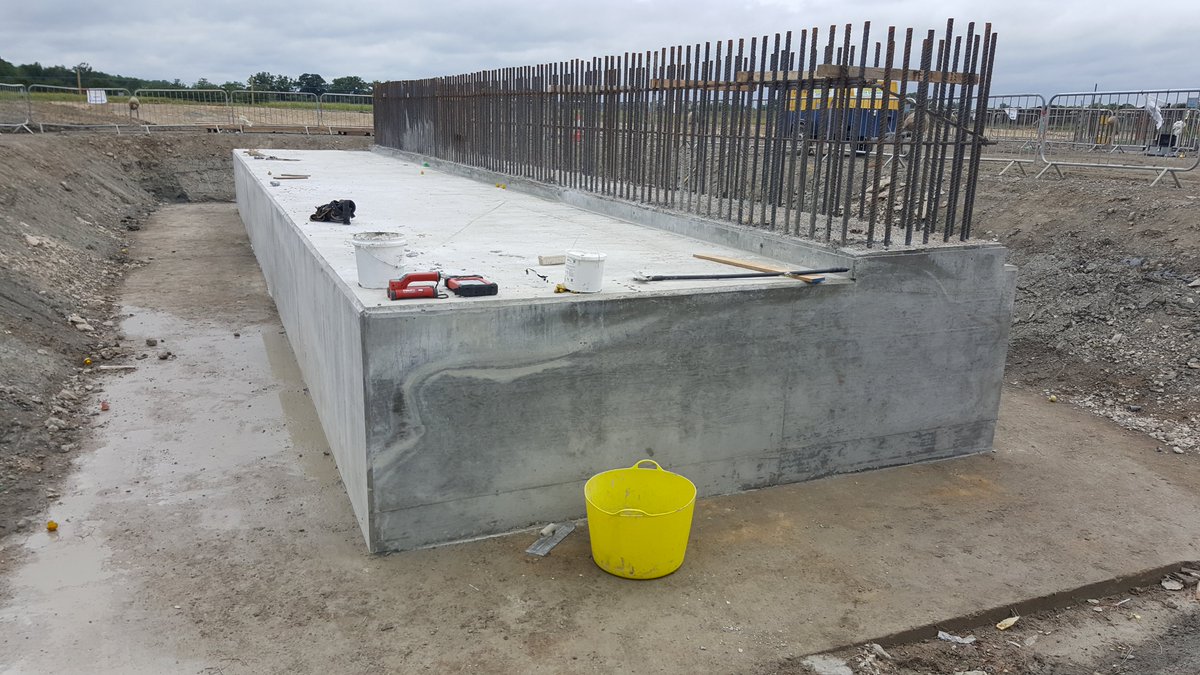
The concrete is poured and shutters removed, leaving starter bars ready for the wall - bridge span is on right, the weight of backfill will sit on the slab top on left on reduce moment (rotating) forces. 35/
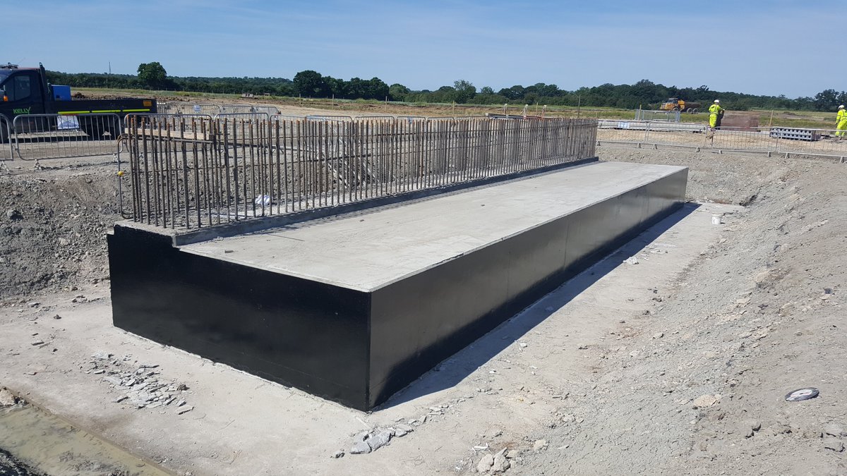
Prior to backfill the pilecap is painted with bitumen waterpoofing paint to protect against moisture and chemical attack (the top is left for later so the paint isn& #39;t damage by further construction work) 36/
Whilst other works go on we start prefabricating the abutment wall steel on the ground - again this is safer & easier than doing it up in the air; although I& #39;ve never done it before with such large areas as it can be tricky to match up with starter bars when lifted into place 37/
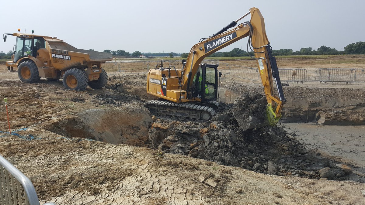
The abutment wingwalls are made of reinforced earth & blockwork; they need a stone foundation so we excavate for this, removing the topsoil & alluvial ground to the good blue fine clay beneath. Wingwalls will retain the embankment of A14 slip on top of bridge 38/
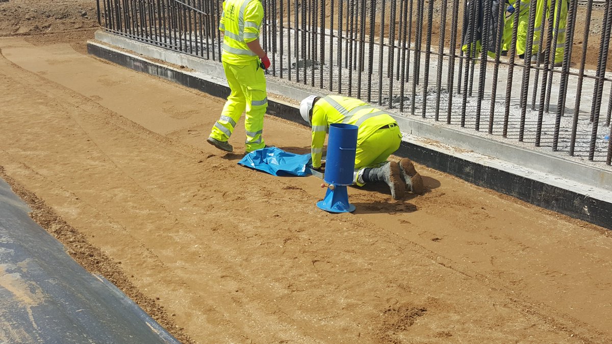
We backfill with an engineered Class 6 aggregate which is very fine to allow it to be compacted well. Pic 2 shows the "Sand Replacement Test" which is a compaction test; it takes ages so very quickly we switched to using a Nuclear Density Gauge which is far faster 39/
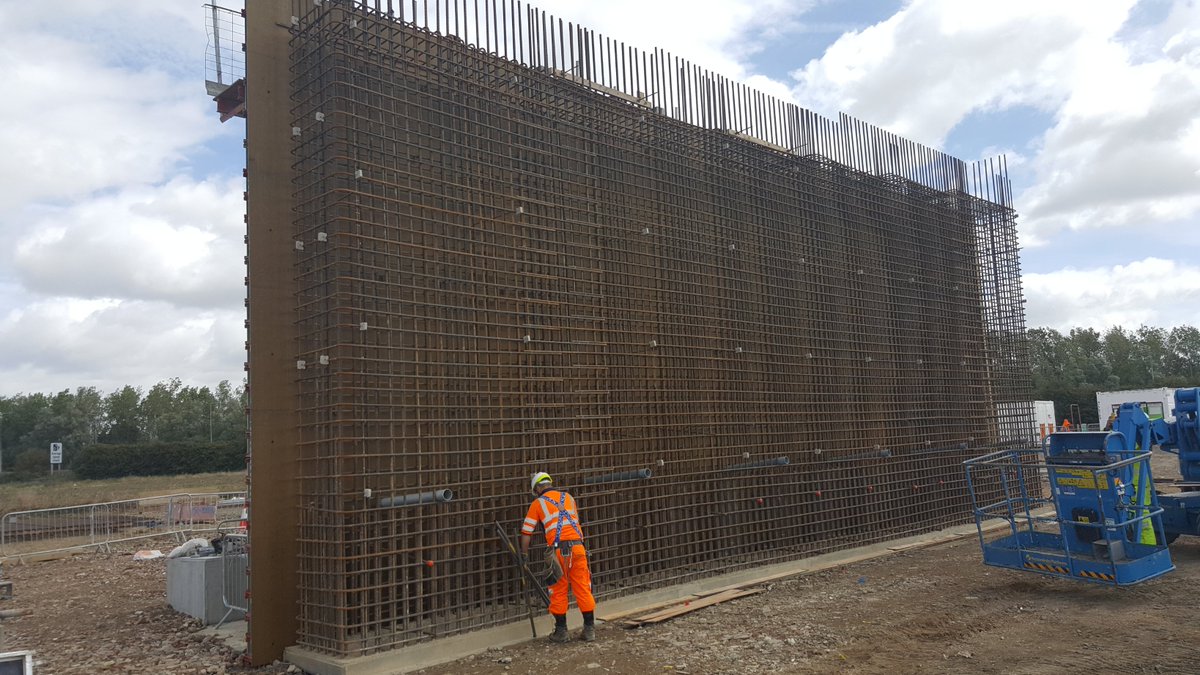
The back shutter for the abutment wall is lifted into place and the prefabricated steel mat is lifted and tied to the starter bars. U-bars at either end fixed to tie back & front mats together and voila, the reinforcement for the abutment wall is complete! 40/
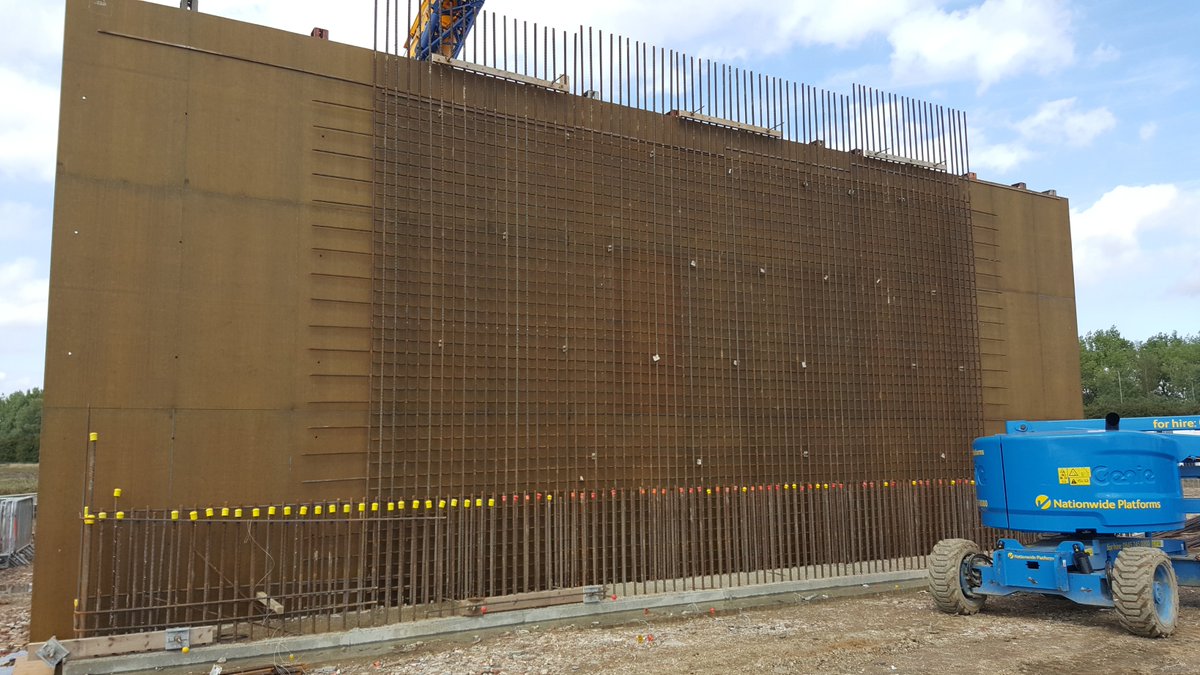
Concrete is poured and after curing the shutters are removed - feature groove to discourage graffiti. Rebar at top is the starter bars for the deck. See the top of wall is stepped? This for the beams which sit at different levels due to camber of the A14 slip road 41/
Looking west/north from BN24 along the A1307 Local Access Road which goes under the bridge. The roundabout allows a slip road from the LAR to join the A14 northbound. The LAR separates slow/vulnerable traffic like tractors & cyclists from HGVs and cars on main A14 42/
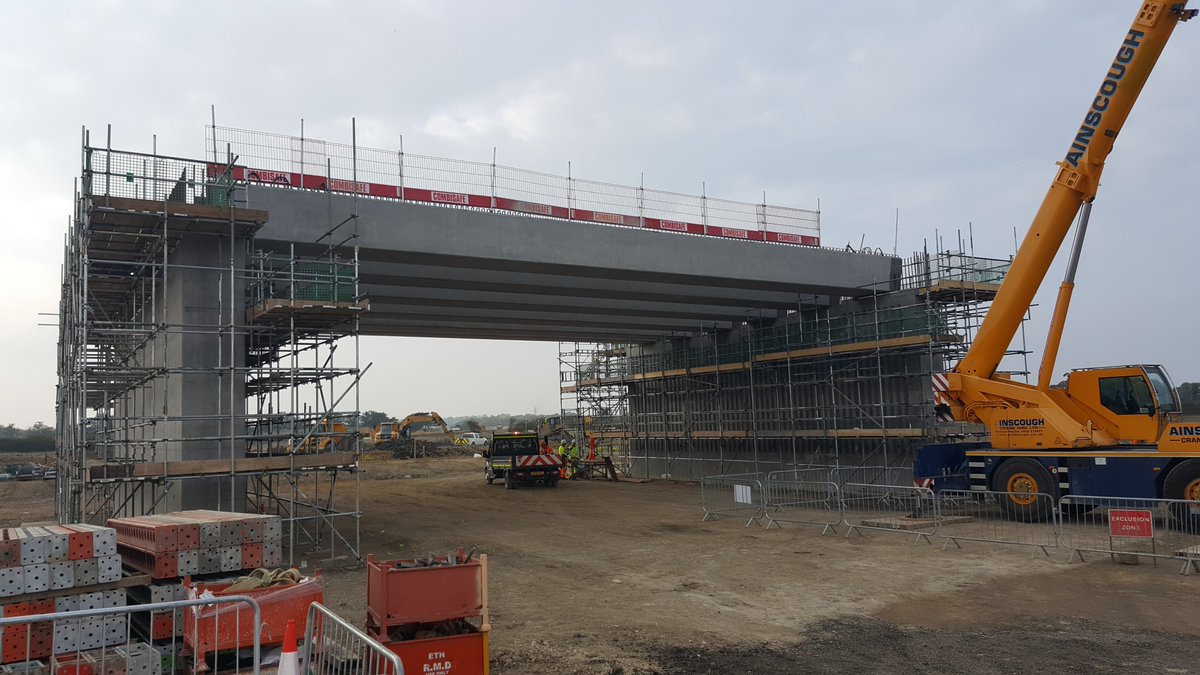
Beams are landed; these are & #39;W& #39;-Type beams precast in Ireland and ferried over, they are & #39;hollow& #39; to reduce weight so very efficient 43/
Next on the beams are the grey panels made of glass-reinforced plastic fibres, they form the soffit to the deck, concrete will be placed on this. The small hoops of rebar are shear links that connect the bridge beams to the deck. The two pointy strands are lifting points 44/

 Read on Twitter