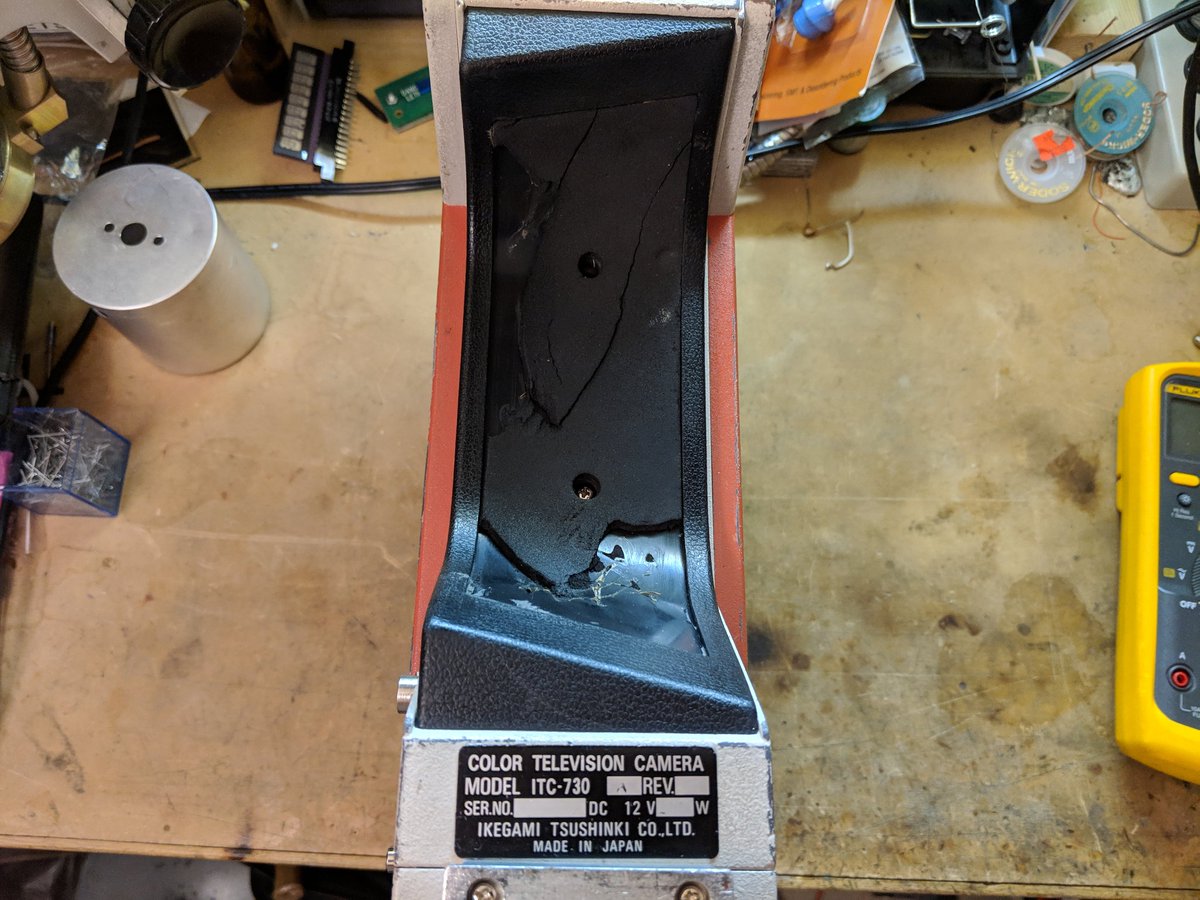
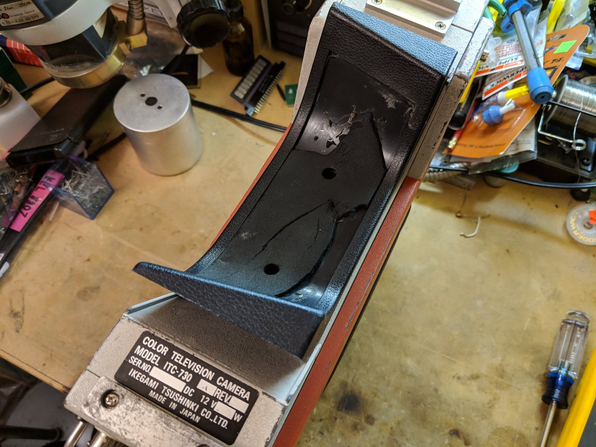
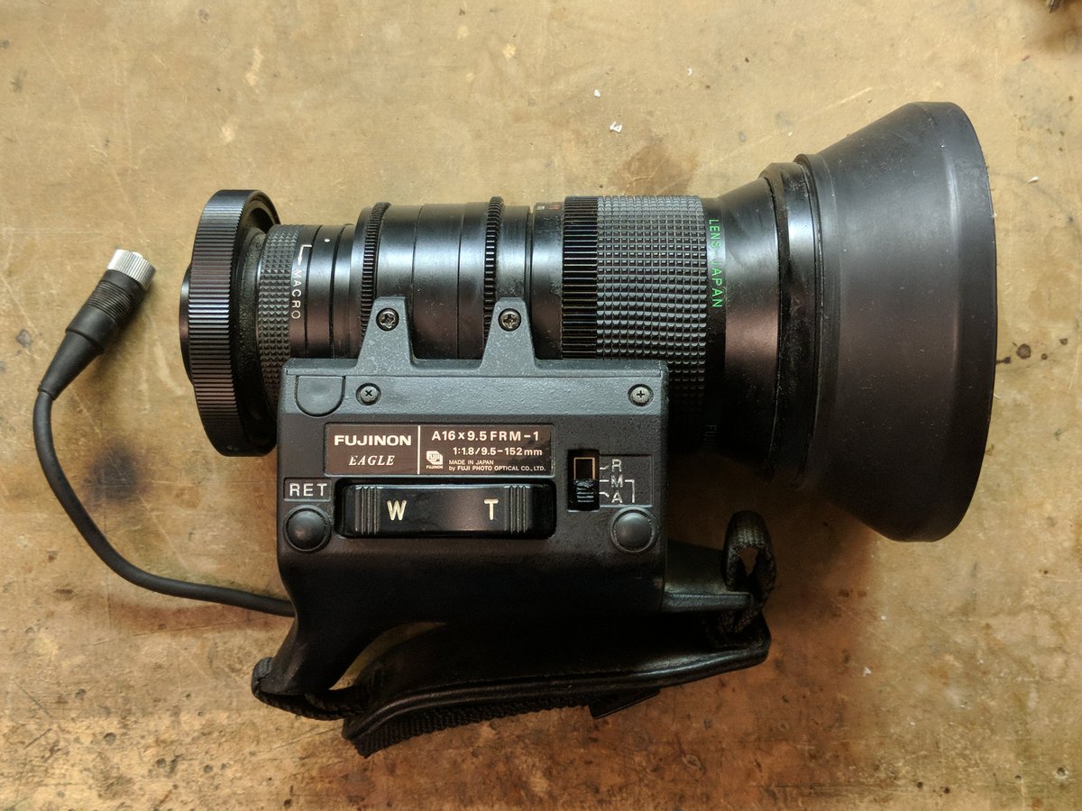
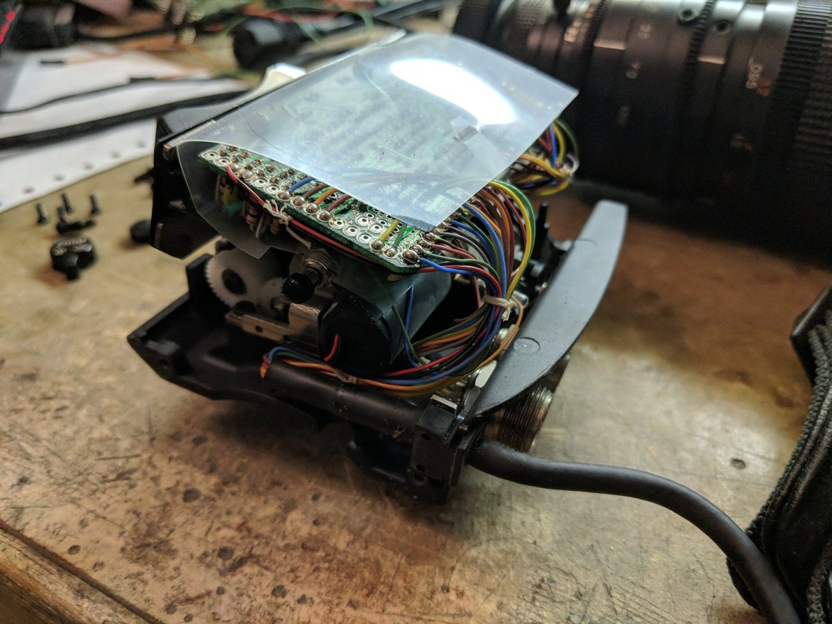
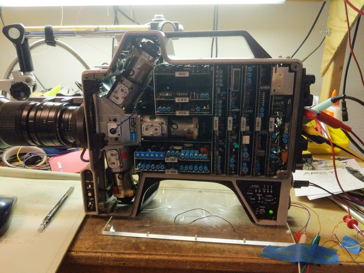
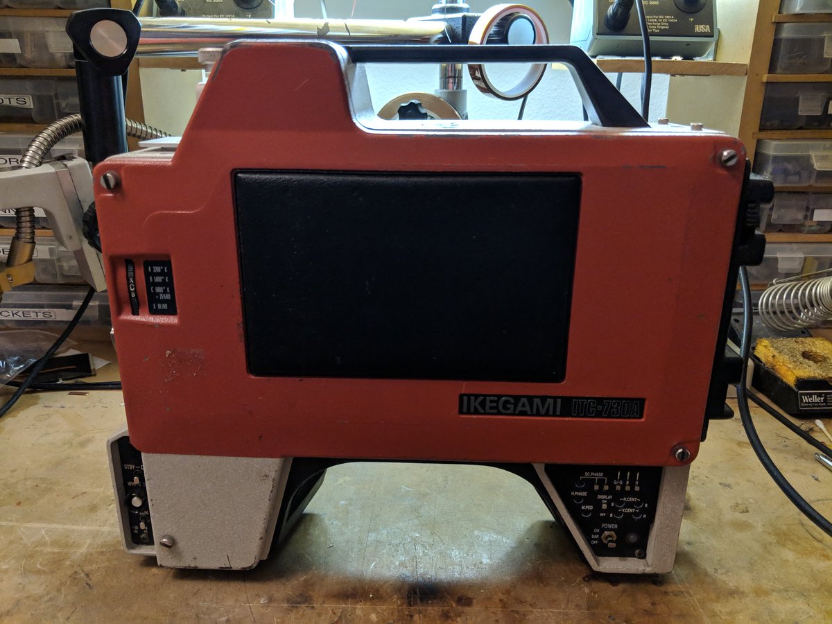
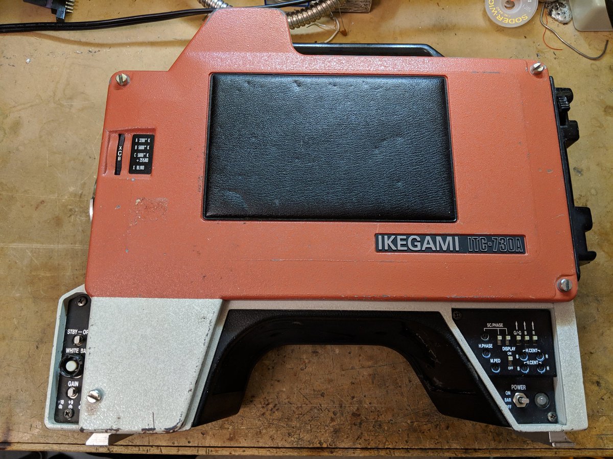
let& #39;s take apart this old TV camera!  https://abs.twimg.com/emoji/v2/... draggable="false" alt="📹" title="Videokamera" aria-label="Emoji: Videokamera">
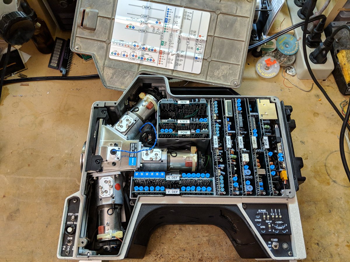
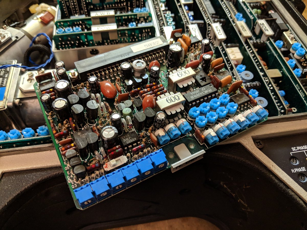
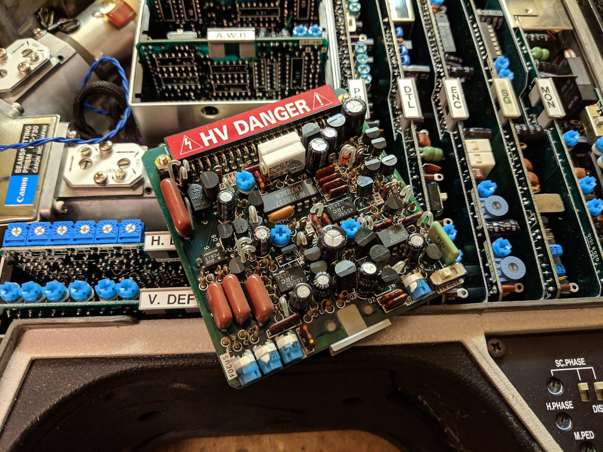
woah, that& #39;s a lot of boards
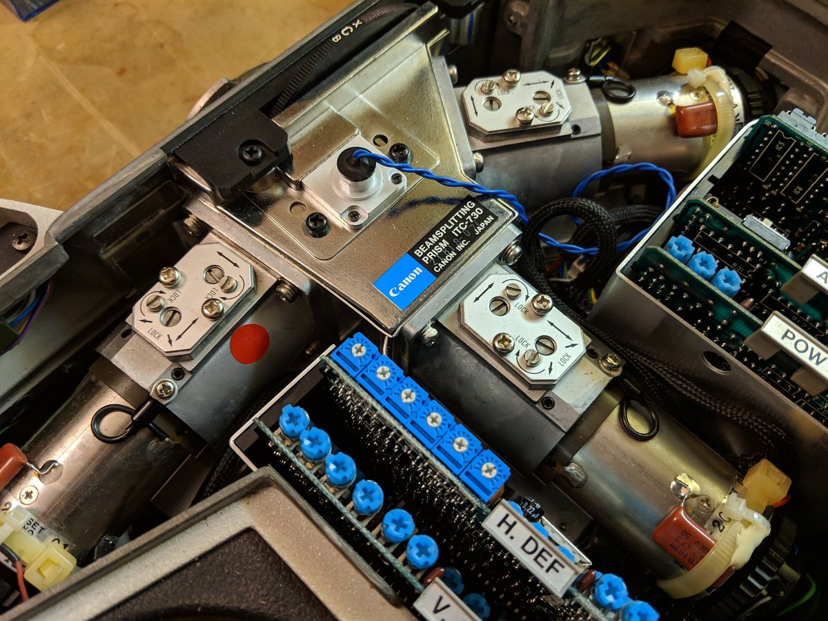
the light from the lens goes through a beam splitting prism and three color filters. each filtered image goes into a vidicon tube. notice all the adjustment screws? yeah what a pain to align.
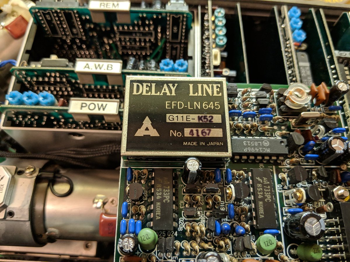
there& #39;s a delay line on this board
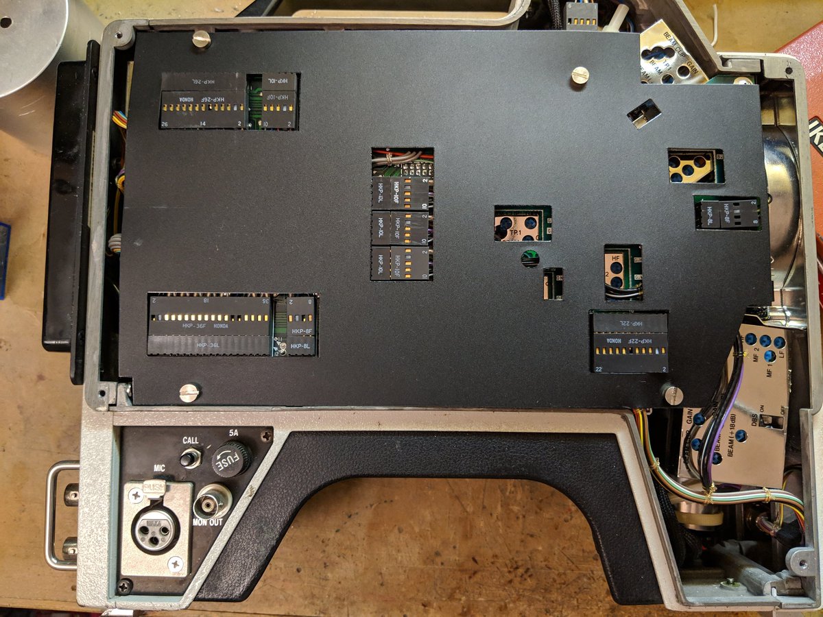
the other side opens up too. more trimmers.  https://abs.twimg.com/emoji/v2/... draggable="false" alt="🤪" title="Zany face" aria-label="Emoji: Zany face">
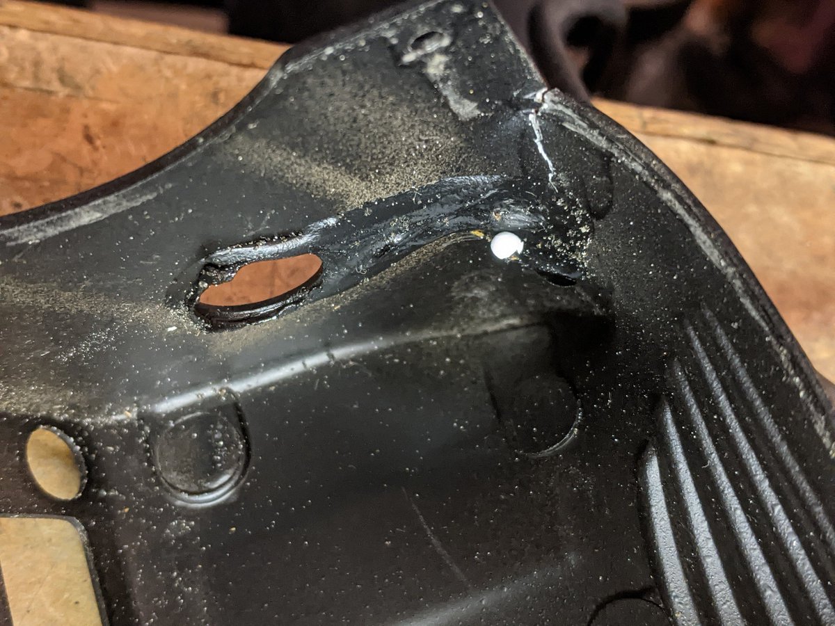
looks like this button& #39;s rubber cap melted
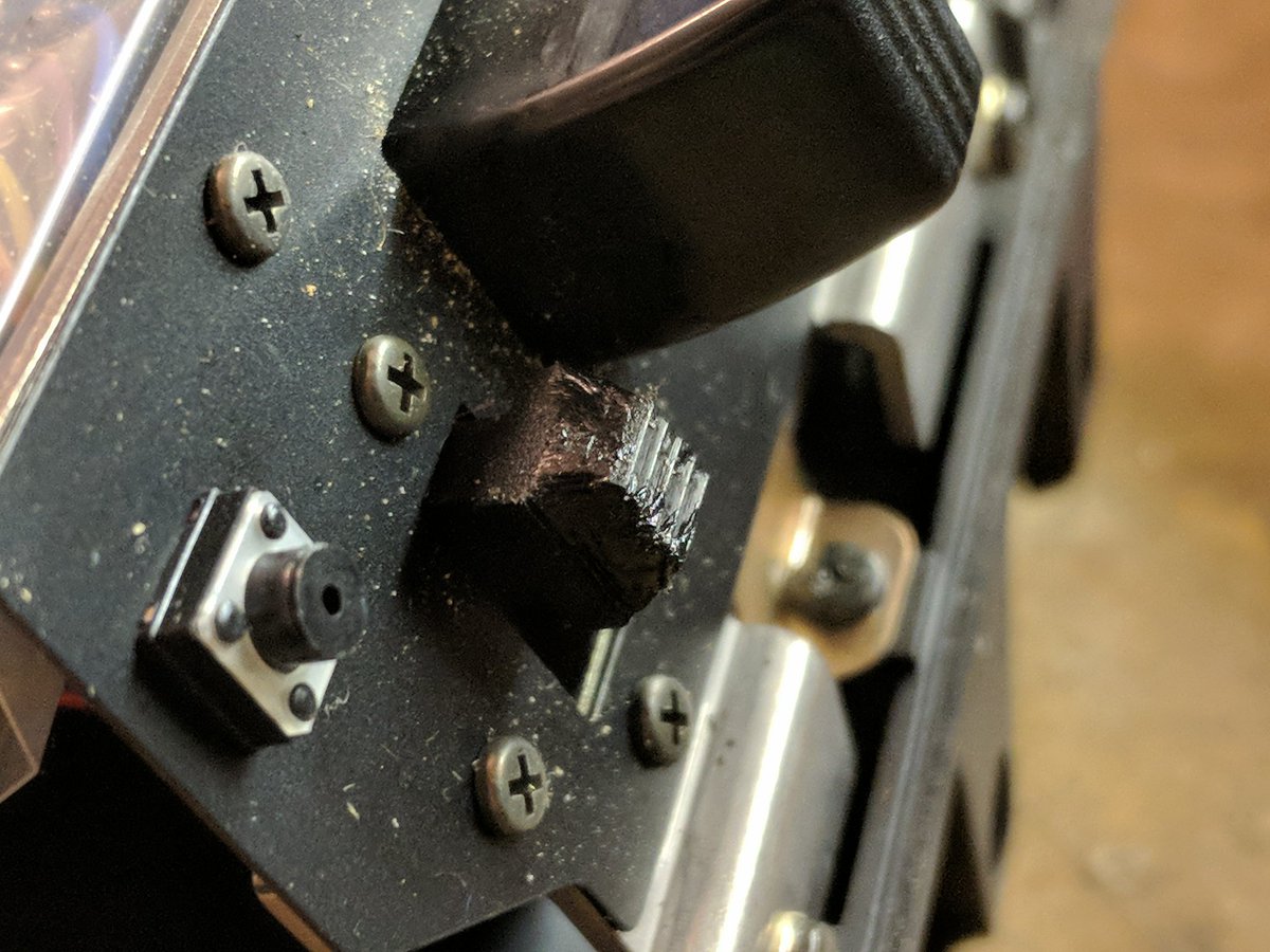
and this slide switch cap is in the process of melting. I& #39;ll try to 3D print a replacement.
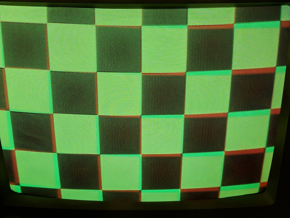
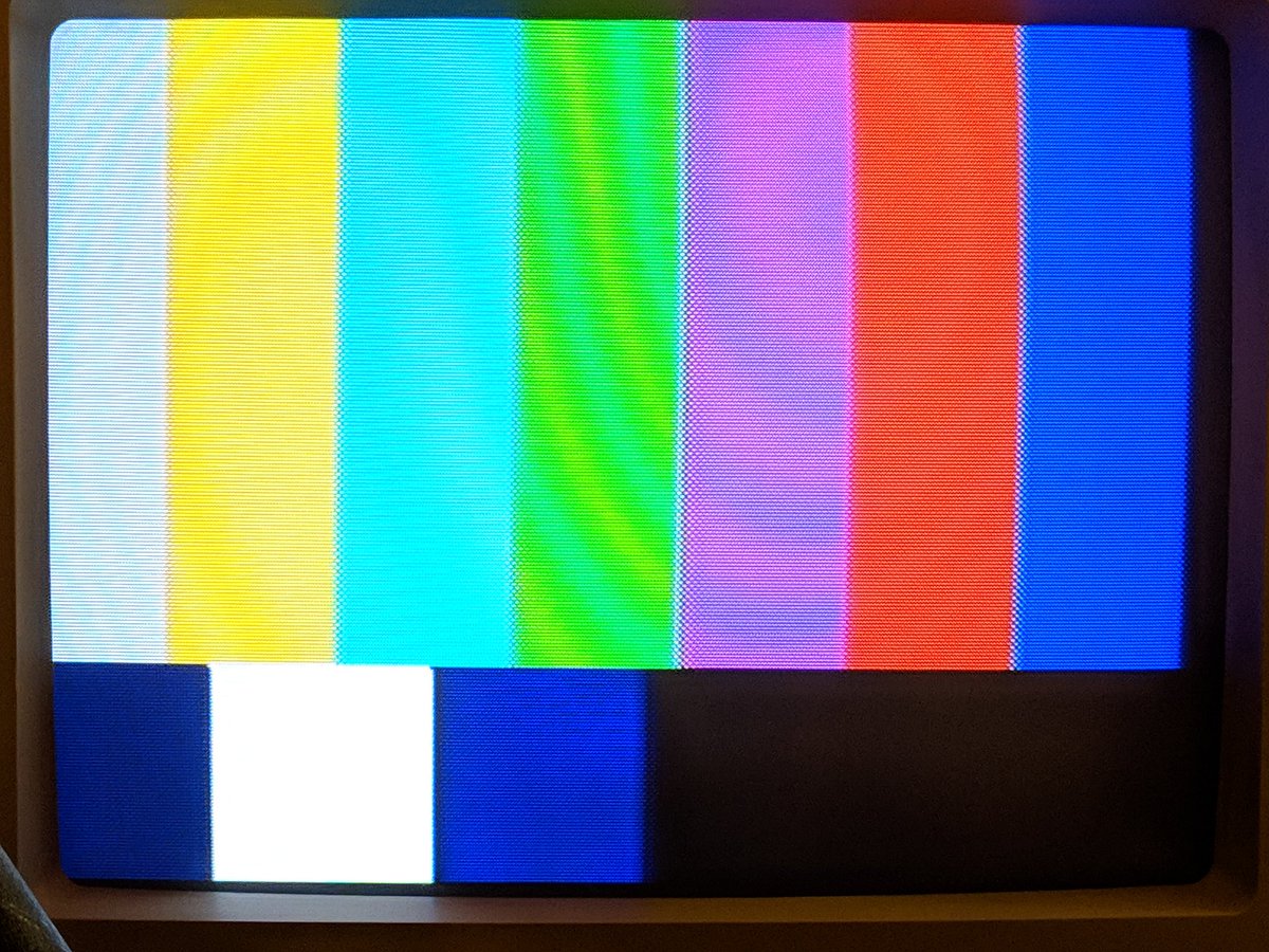
wow it& #39;s really far off
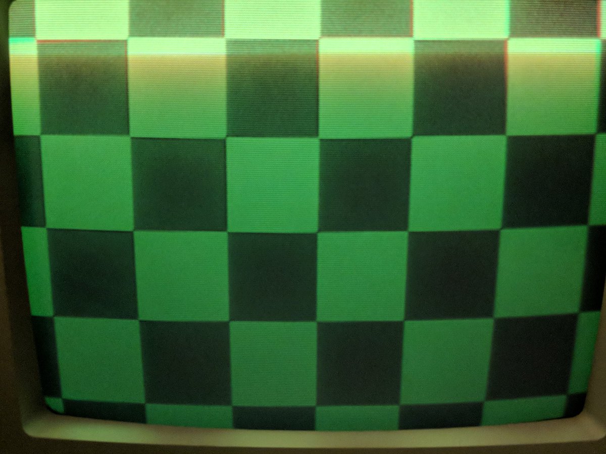
better. I& #39;m doing red first, blue next
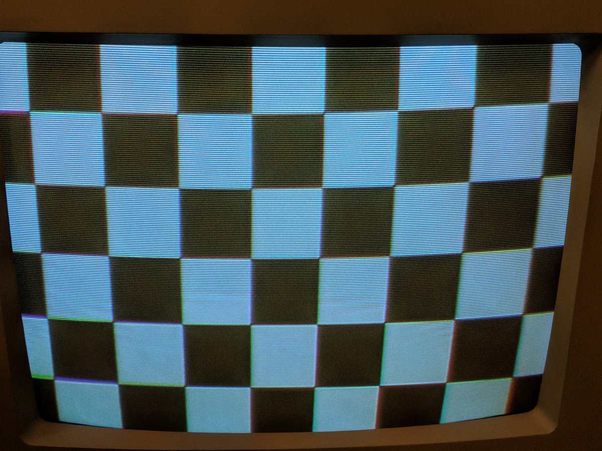
i& #39;m consulting an expert now. he once told me how he had to spend hours adjusting similar cameras, so now i get to experience that too, only without any time pressure.
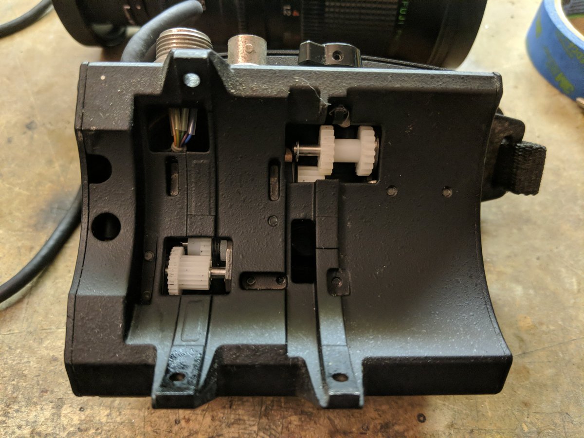
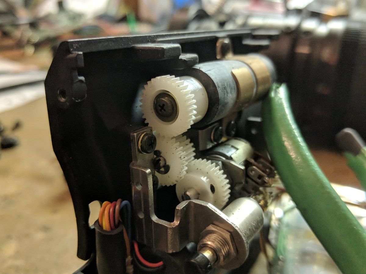
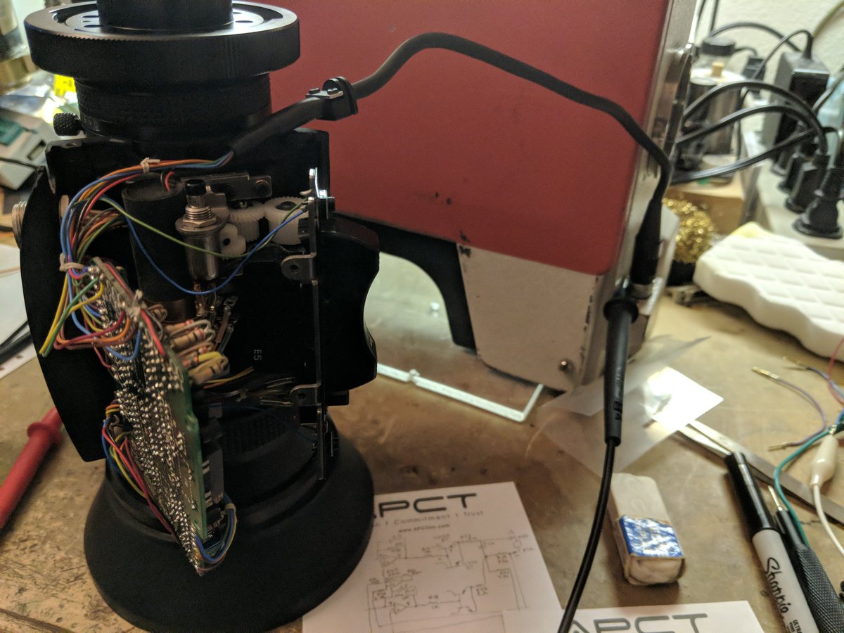
working on fixing the lens electronics. the zoom buttons don& #39;t seem to do anything
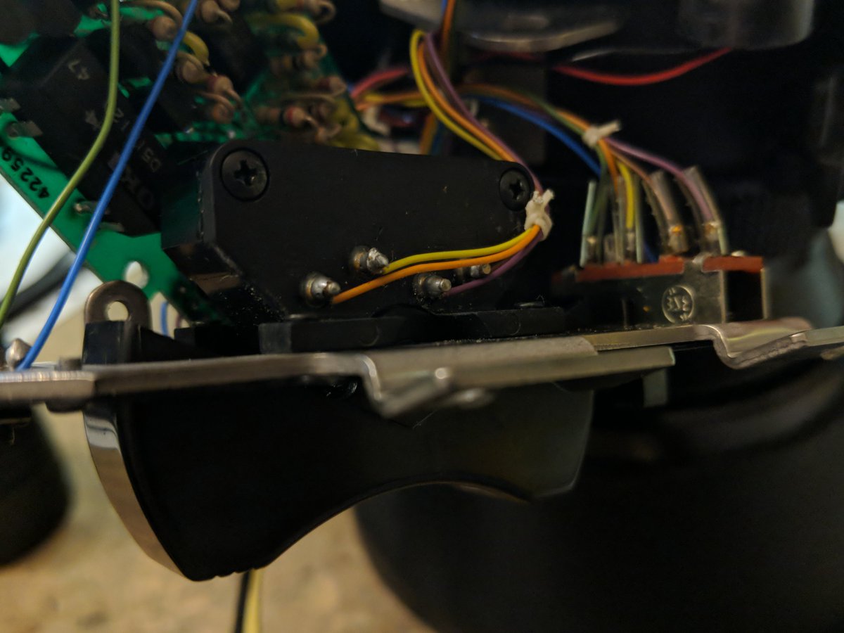
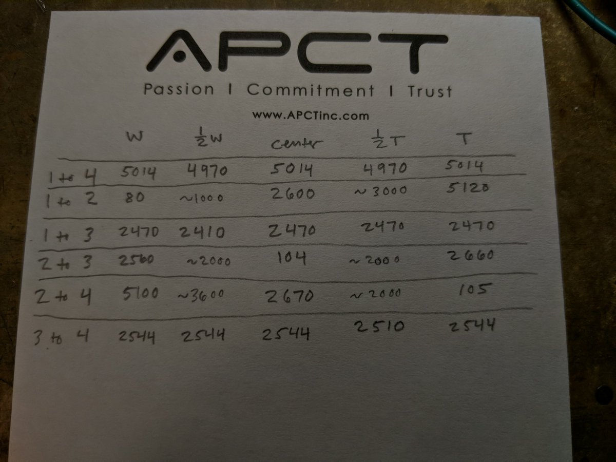
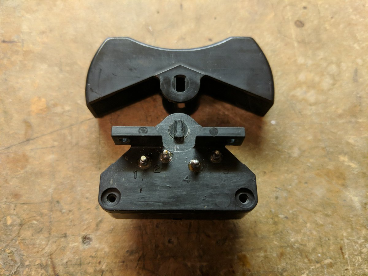
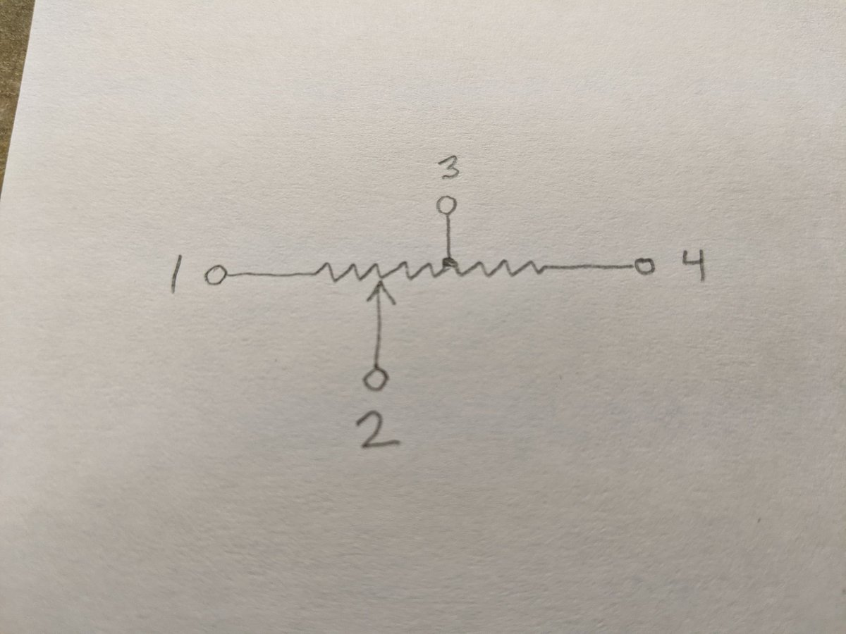
ok here& #39;s an electrical puzzle. this center-sprung zoom button has 4 terminals and must have potentiometers inside, but how are they connected? I made a table of resistances for all combinations of pins with the control in different positions. can you figure it out?
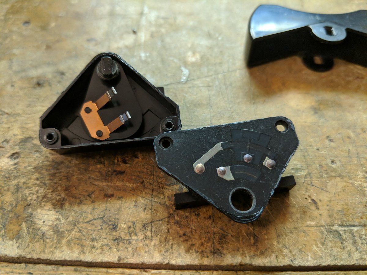
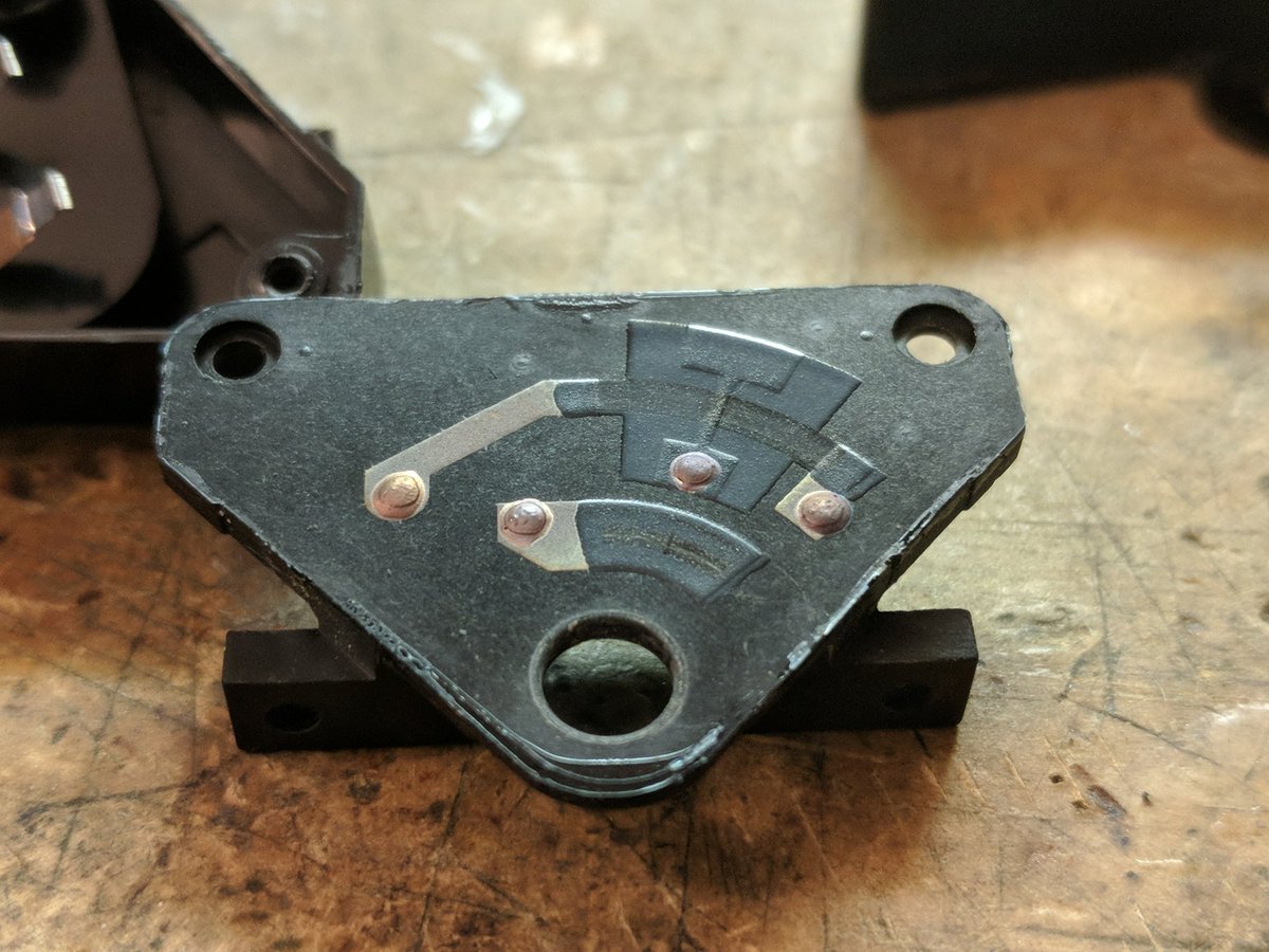
I can& #39;t open the potentiometer without damaging it since it& #39;s glued shut. this is really bothering me now lol
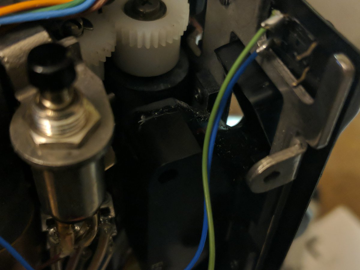
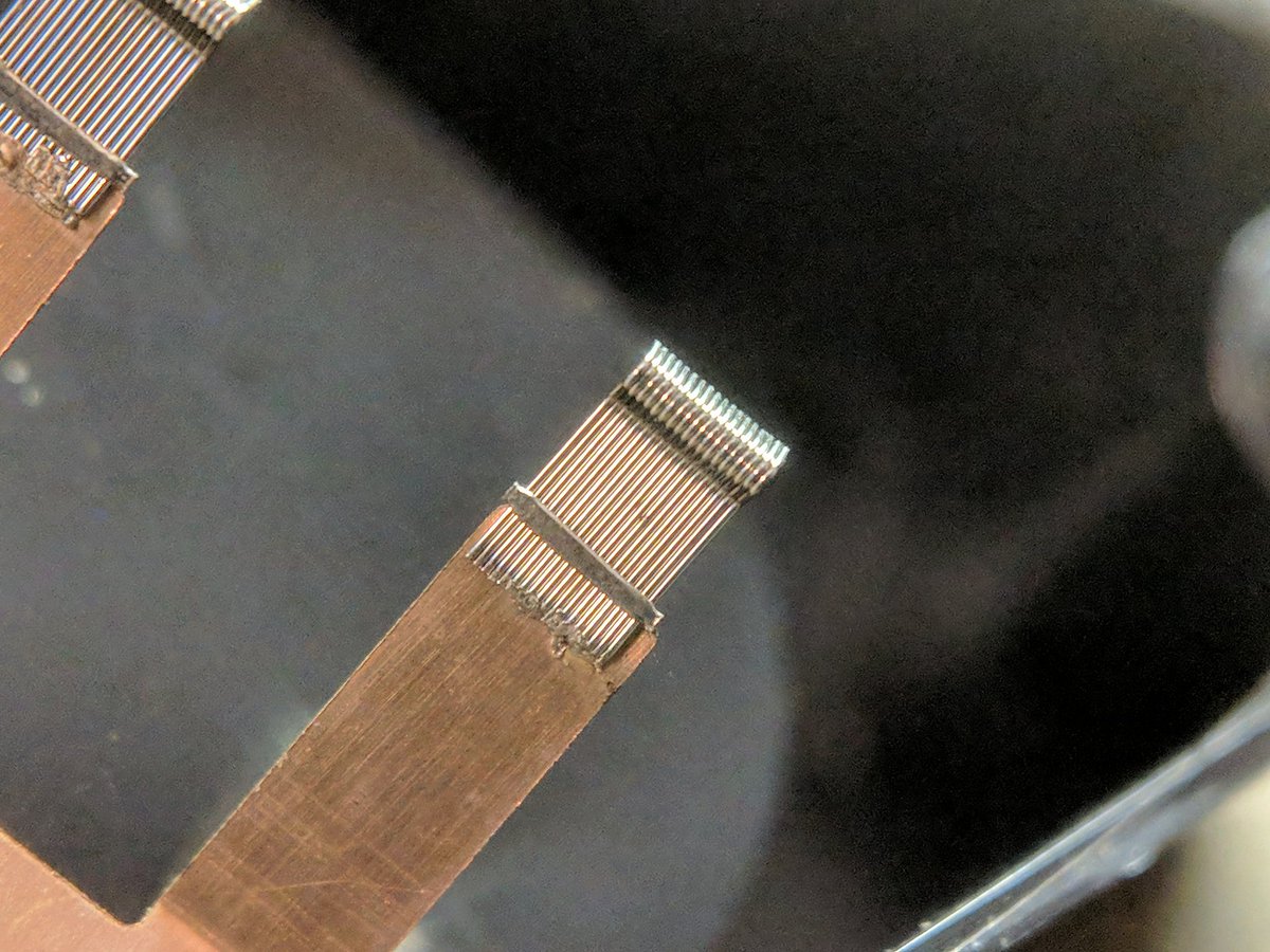
check out the brushes! usually it& #39;s all stamped out of the same springy copper. this must have been expensive.

 Read on Twitter
 " title="let& #39;s take apart this old TV camera! https://abs.twimg.com/emoji/v2/... draggable="false" alt="📹" title="Videokamera" aria-label="Emoji: Videokamera">" class="img-responsive" style="max-width:100%;"/>
 HV DANGER https://abs.twimg.com/emoji/v2/... draggable="false" alt="⚠️" title="Warnsignal" aria-label="Emoji: Warnsignal">" title="https://abs.twimg.com/emoji/v2/... draggable="false" alt="⚠️" title="Warnsignal" aria-label="Emoji: Warnsignal"> HV DANGER https://abs.twimg.com/emoji/v2/... draggable="false" alt="⚠️" title="Warnsignal" aria-label="Emoji: Warnsignal">" class="img-responsive" style="max-width:100%;"/>
 " title="the other side opens up too. more trimmers. https://abs.twimg.com/emoji/v2/... draggable="false" alt="🤪" title="Zany face" aria-label="Emoji: Zany face">" class="img-responsive" style="max-width:100%;"/>
